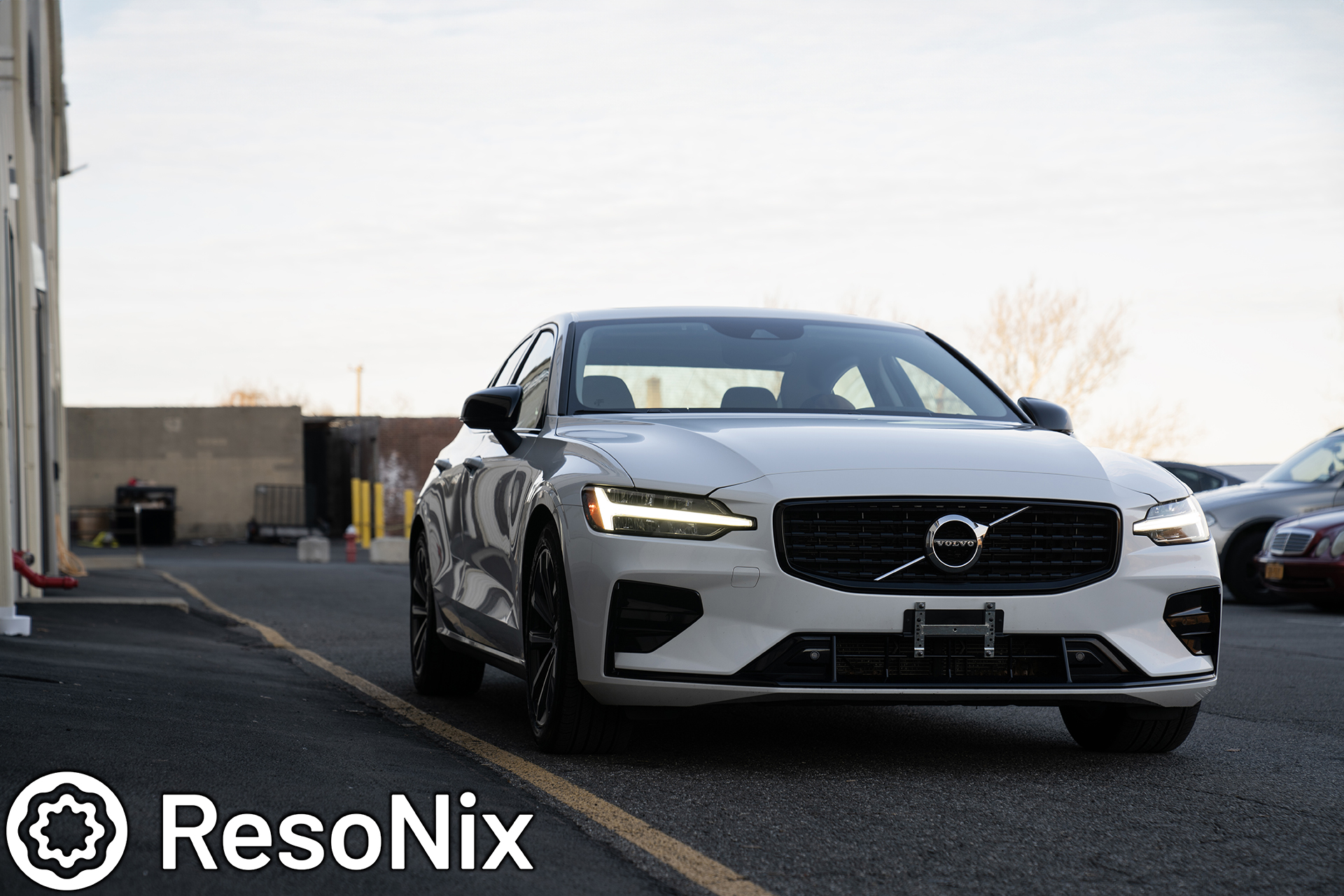
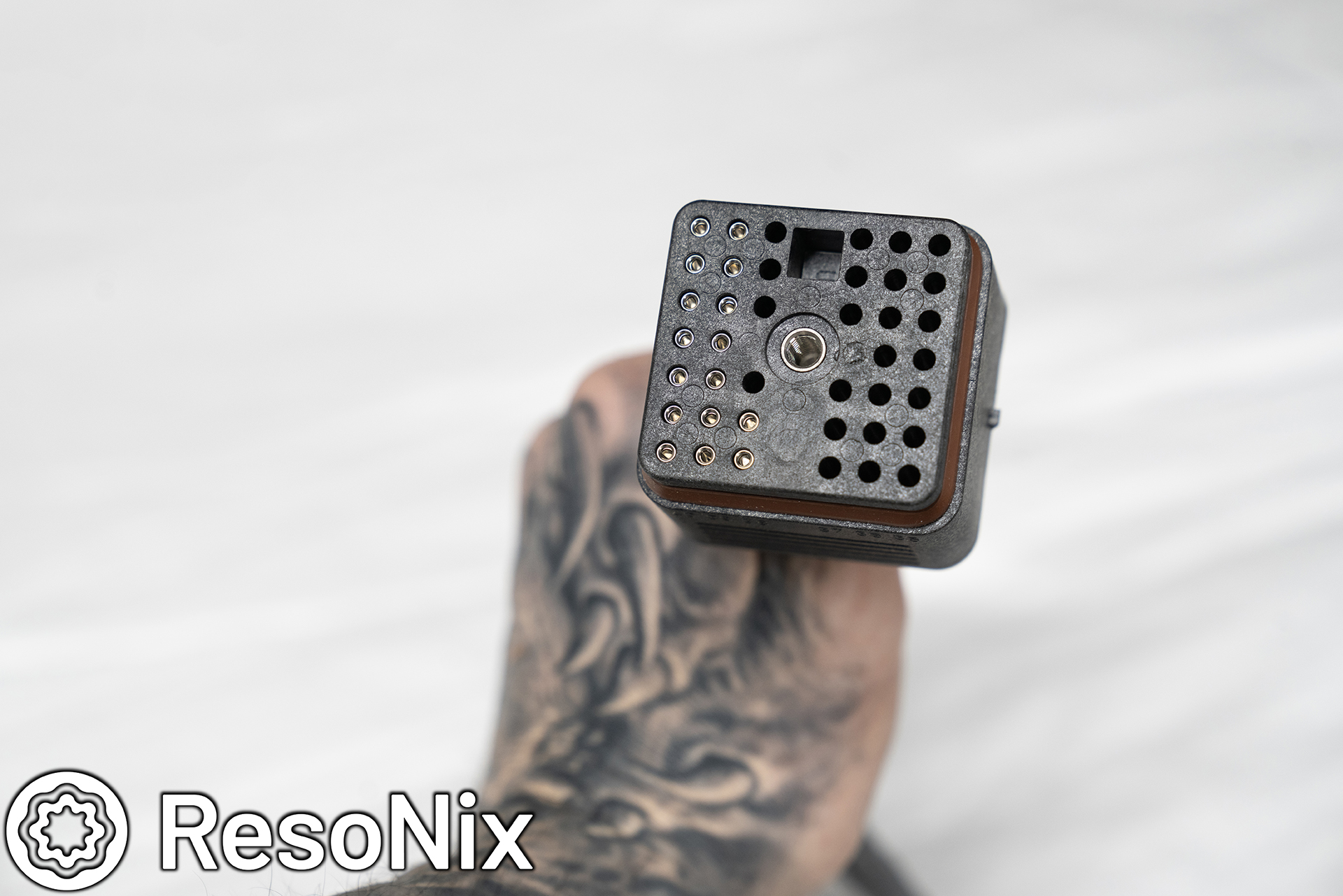
2019 Volvo S60 R-Design – ResoNix Sound Solutions Demo Vehicle Car Audio Installation
2019 Volvo S60 R-Design – ResoNix Sound Solutions Demo Sound System Elevating Sound and Functionality: The Ultimate 2019 Volvo S60
Hello everyone, long time no see 🙂
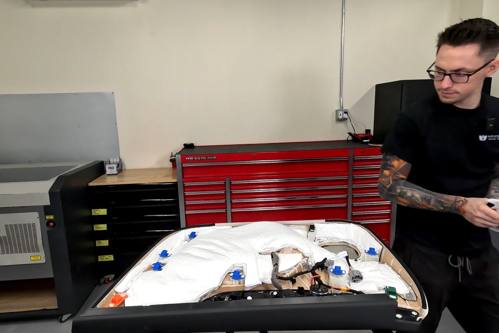
Nick Apicella of ResoNix Sound Solutions & Apicella Auto Sound here with our very first full car audio install in our new and finally fully outfitted shop. For those that are unaware, I have decided to make ResoNix Sound Solutions my full time gig, and do Apicella Auto Sound car audio installs on the side. This allows me to still do what I love, but to not take it as a means to put food on the table and I can have more fun with it, and take more time with it, meaning I can get even more detailed on my installs without worrying about the clock running out. This means more photos, more videos, more interesting install techniques, and overall better installs and better content since I am only planning on doing jobs that I see myself enjoying. So, if you are looking for a car audio install that is done right and will sound great, feel free to reach out, as it may be a project I’m more than happy to take on. Speaking of enjoying doing installs, lets move on to what we have here.
If you would like to check it out on Facebook, along with the rest of our installs, here is a link to the album.
Facebook Link To The 2022 Volvo S60 Sound System & Sound Deadening Installation
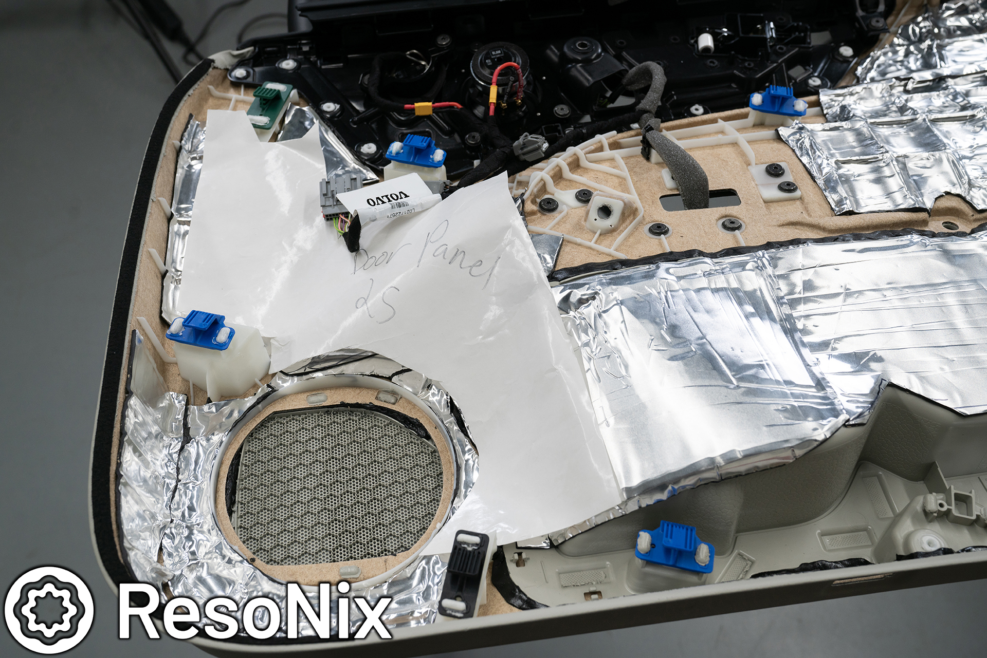
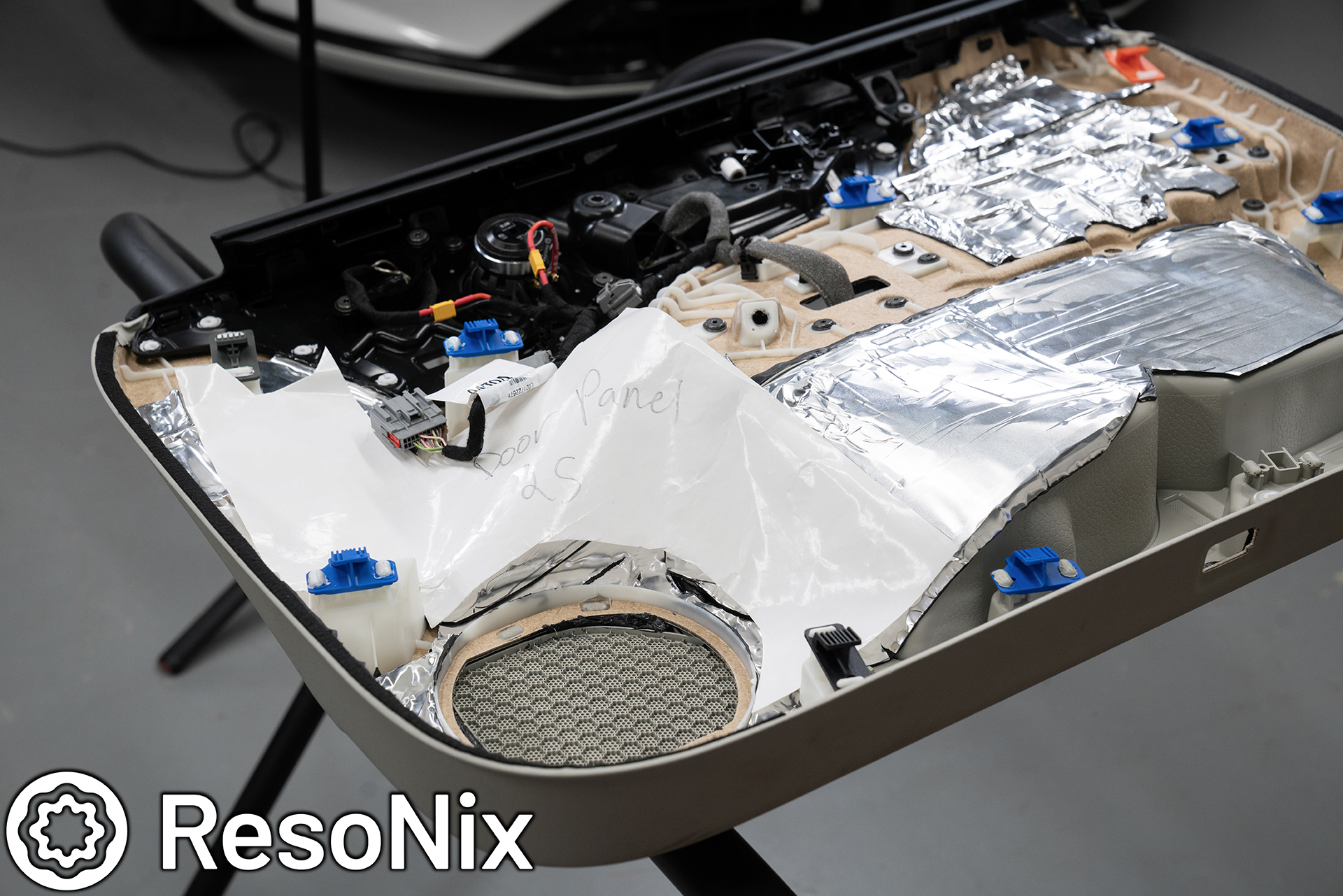
So this is a 2022 Volvo S60, nearly the same exact car that I have, so out of the gate, my interest was piqued. To me, doing a car I already knew very well was the perfect opportunity to get my feet wet in the new shop setup, and as well as getting used to doing the FULL install myself, where as for the past few years I was mostly the office and DSP tuning/OEM integration guy that was doing some install and fabrication work here and there. The owner of the vehicle reached out to me via the contact form on the ResoNix website and mentioned he was getting a new work vehicle and he wanted to upgrade the sound system. The only catch, it is a WORK vehicle. This meant that nothing could be permanently modified, and everything had to be totally concealed, minus adding a bit of show to the trunk, but still keep that functional as well.
The client came by a couple of weeks before his scheduled drop off date and took a listen to my 2019 Volvo S60. Being a top-of-the-line system and installation, it was well beyond his expectations in sound quality as well as output, but I was still able to give him a reference as far as general staging, imaging, tonality, and overall output were concerned. We also had the chance to go over specifics in his car, and I was able to show him how much space would need to be taken up, what the enclosure would look like, how it would all be secured, etc. Everything was all set, and we planned a drop off date. The install included the following products..
. ResoNix Mega CLD Squares Sound Deadening Material
. ResoNix CLD Squares Sound Deadening Material
. ResoNix Fiber Mat 0.5″ Automotive Sound Absorbing Material
. ResoNix Guardian Rear-Wave Door Cavity Midbass Absorber
. ResoNix Fiber Mat 1.0″ Automotive Sound Absorbing Material
. ResoNix Rope – All Purpose Spot Treatment Sound Deadener
. ResoNix CCF Strips – Foam Speaker Rings
. ResoNix VW/Audi OEM Interior Non-Woven Tape
. ResoNix Volvo OEM MOST150 Interface (Coming soon to Volvo, BMW Ethernet and MOST, Mercedes Fiber and Coax MOST, Toyota/Lexus, and Land Rover/Jaguar ethernet and MOST, Cadillac optical and coax, and more.)
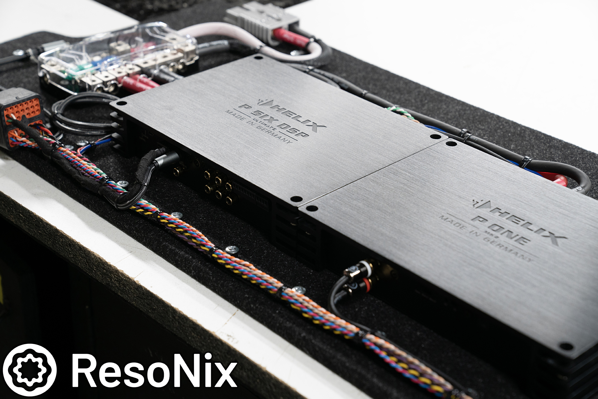
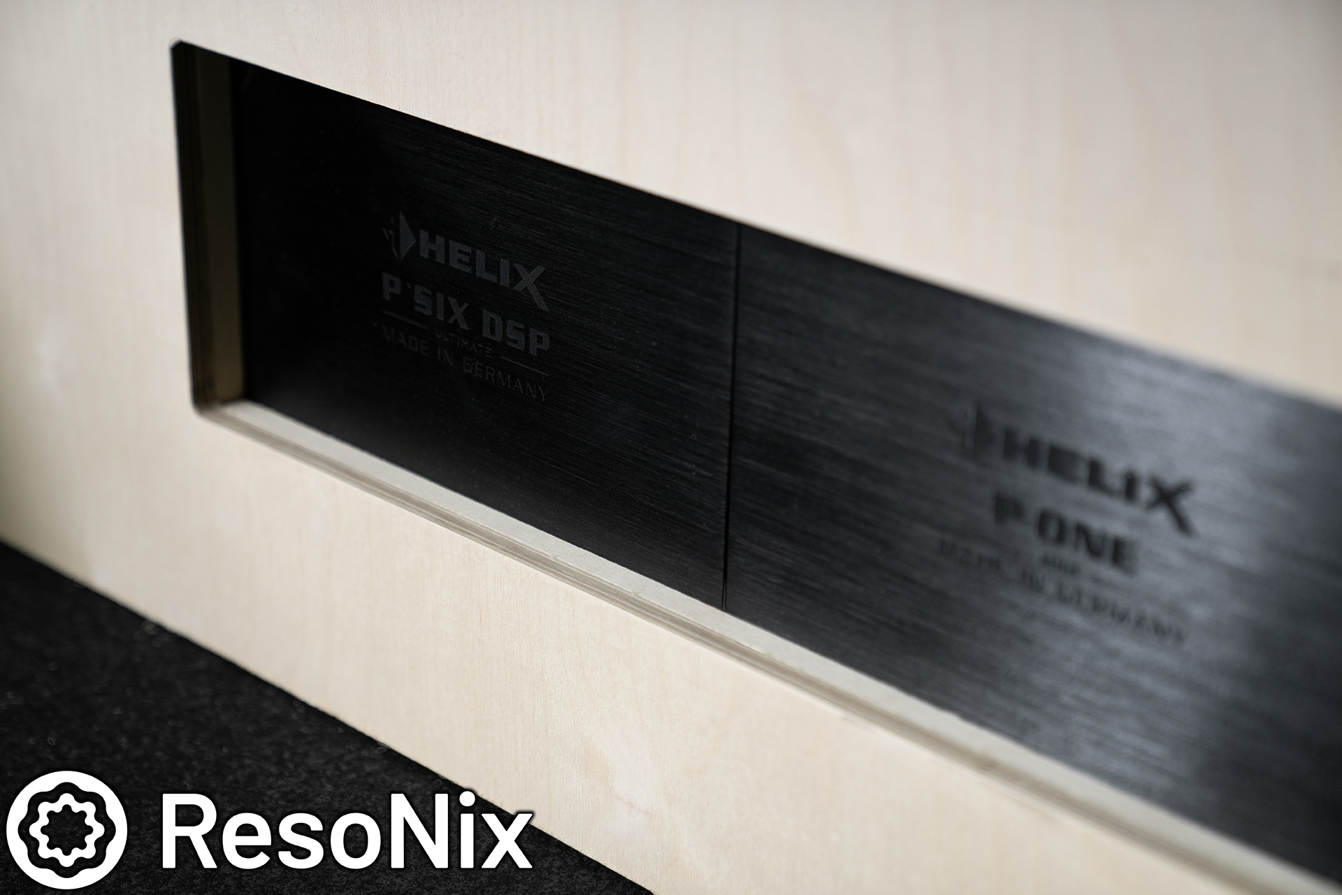
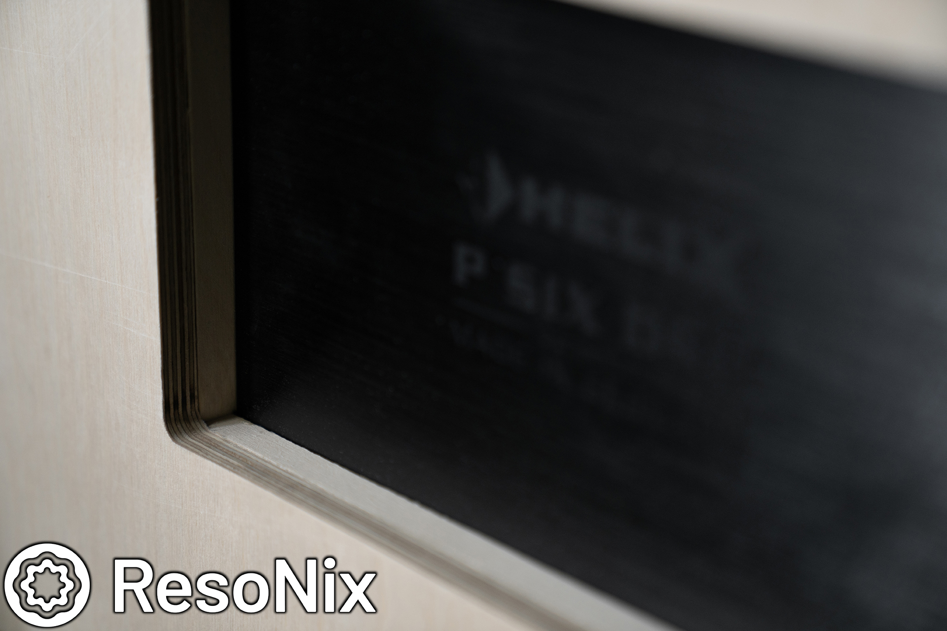
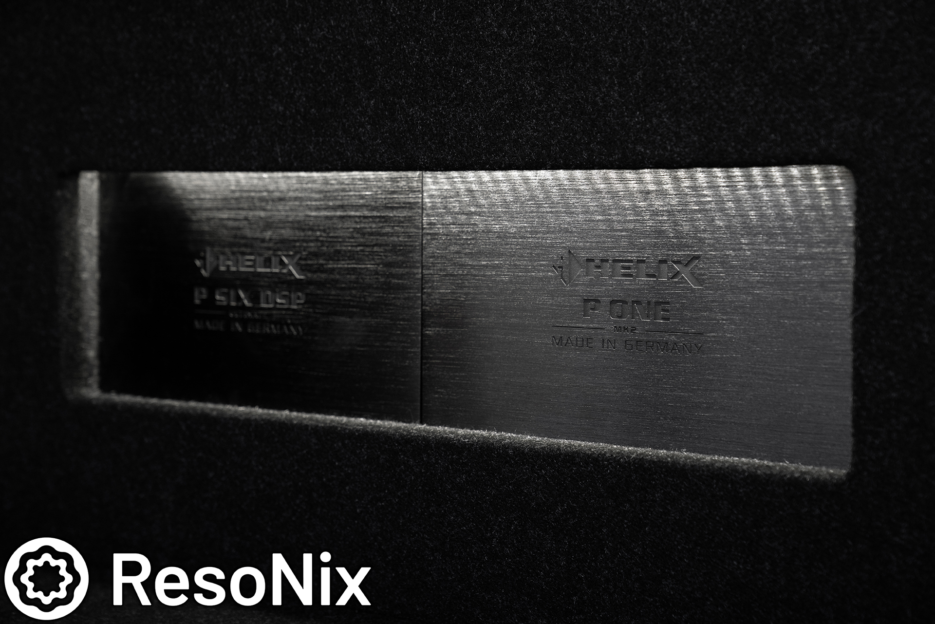
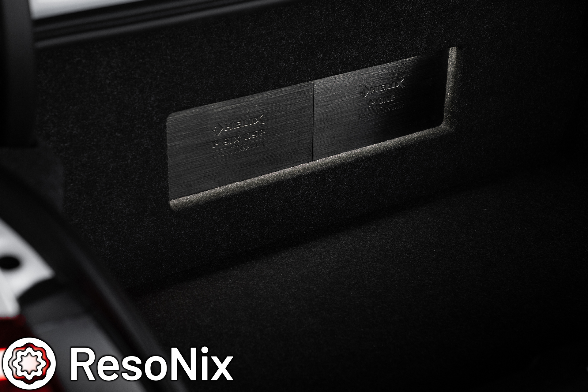
. Helix P Six Ultimate DSP Amplifier
. Helix Conductor DSP Controller
. Helix P One Mk2 Mono Subwoofer Amplifier
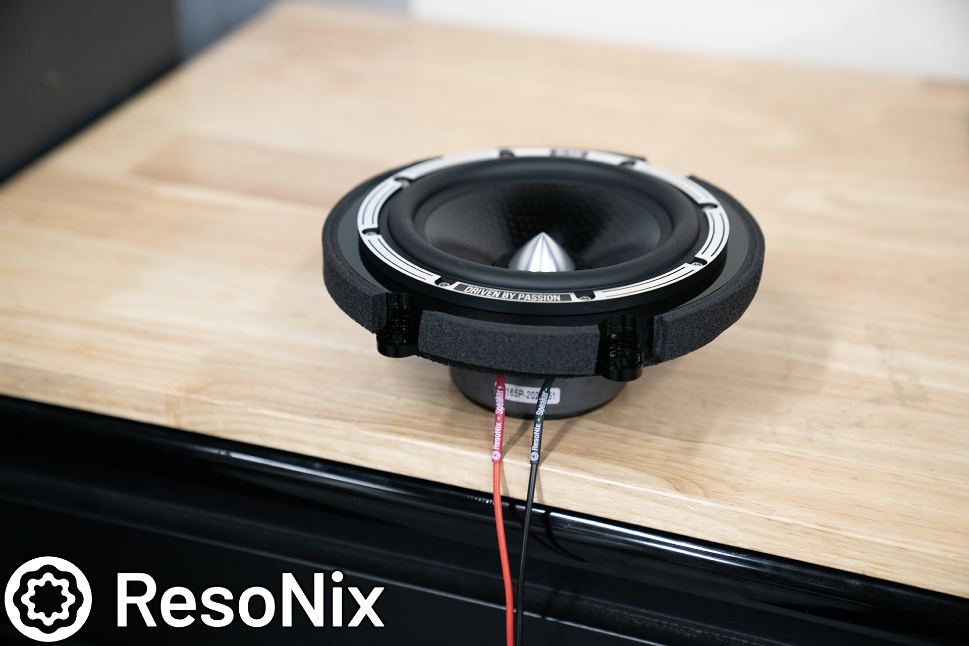
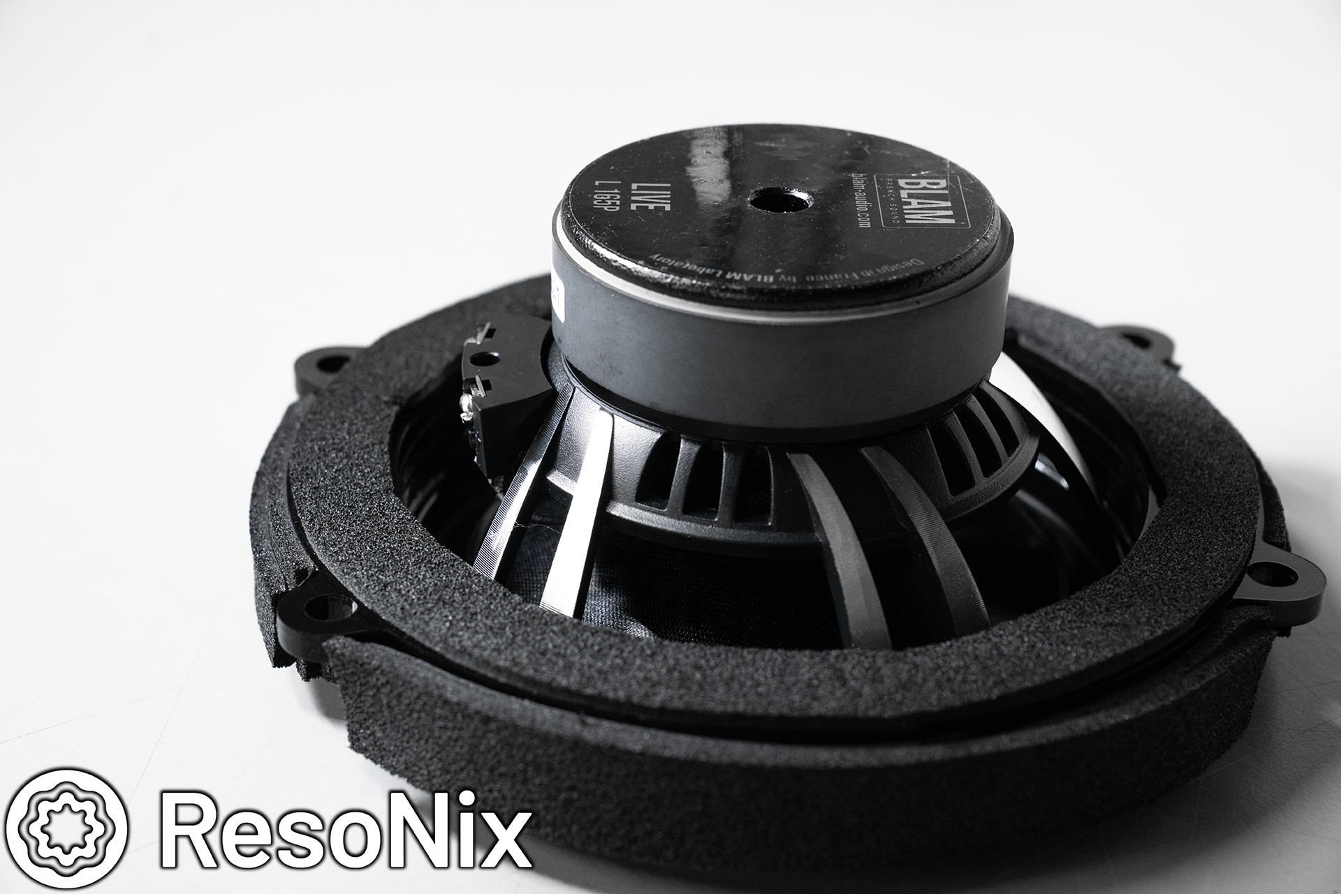
. BLAM Live L165P 6.5″ Midbass & Tweeter
. BLAM Live LFR80 3″ Wideband
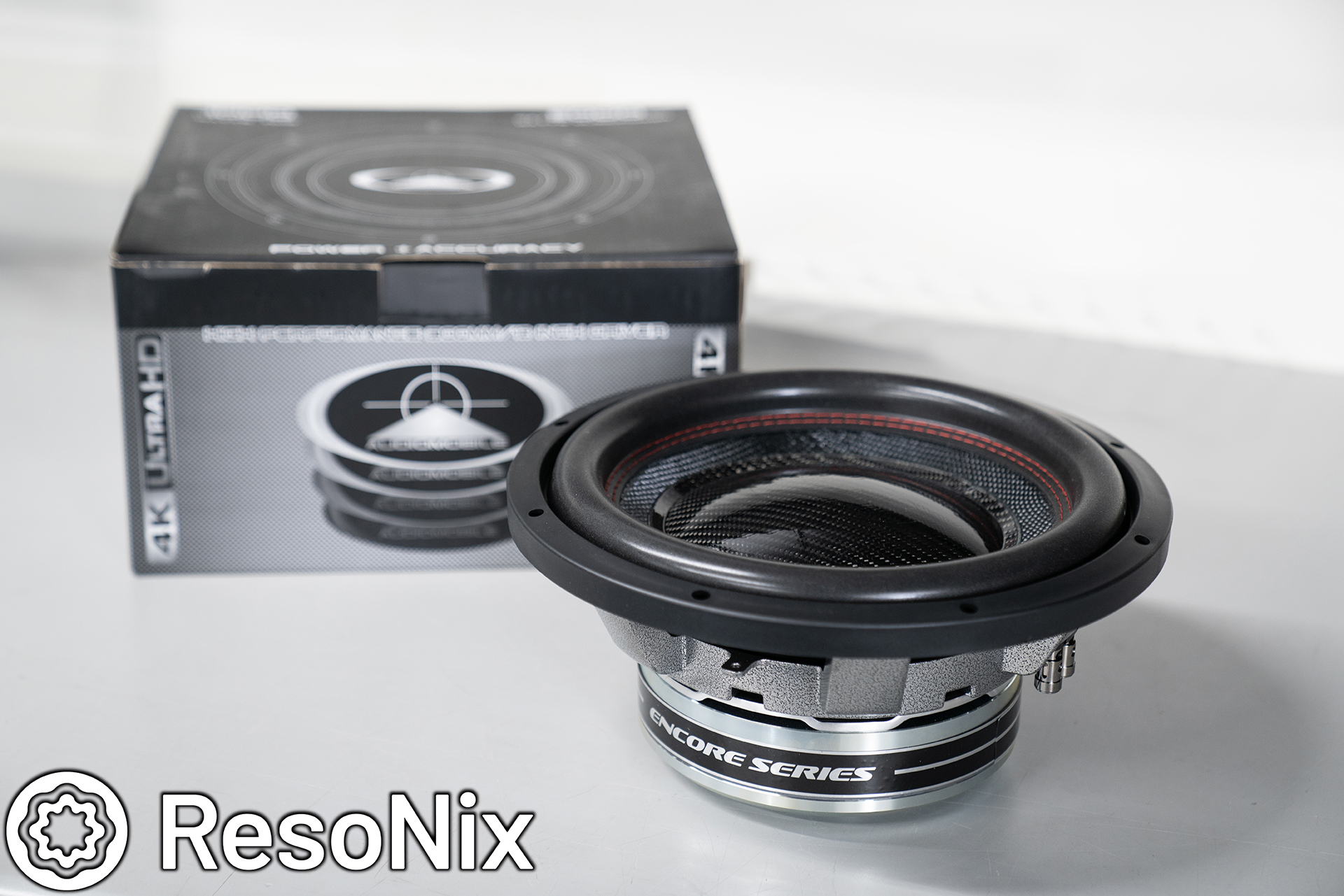
. (2) Audiomobile Encore 12″ D4 subwoofers
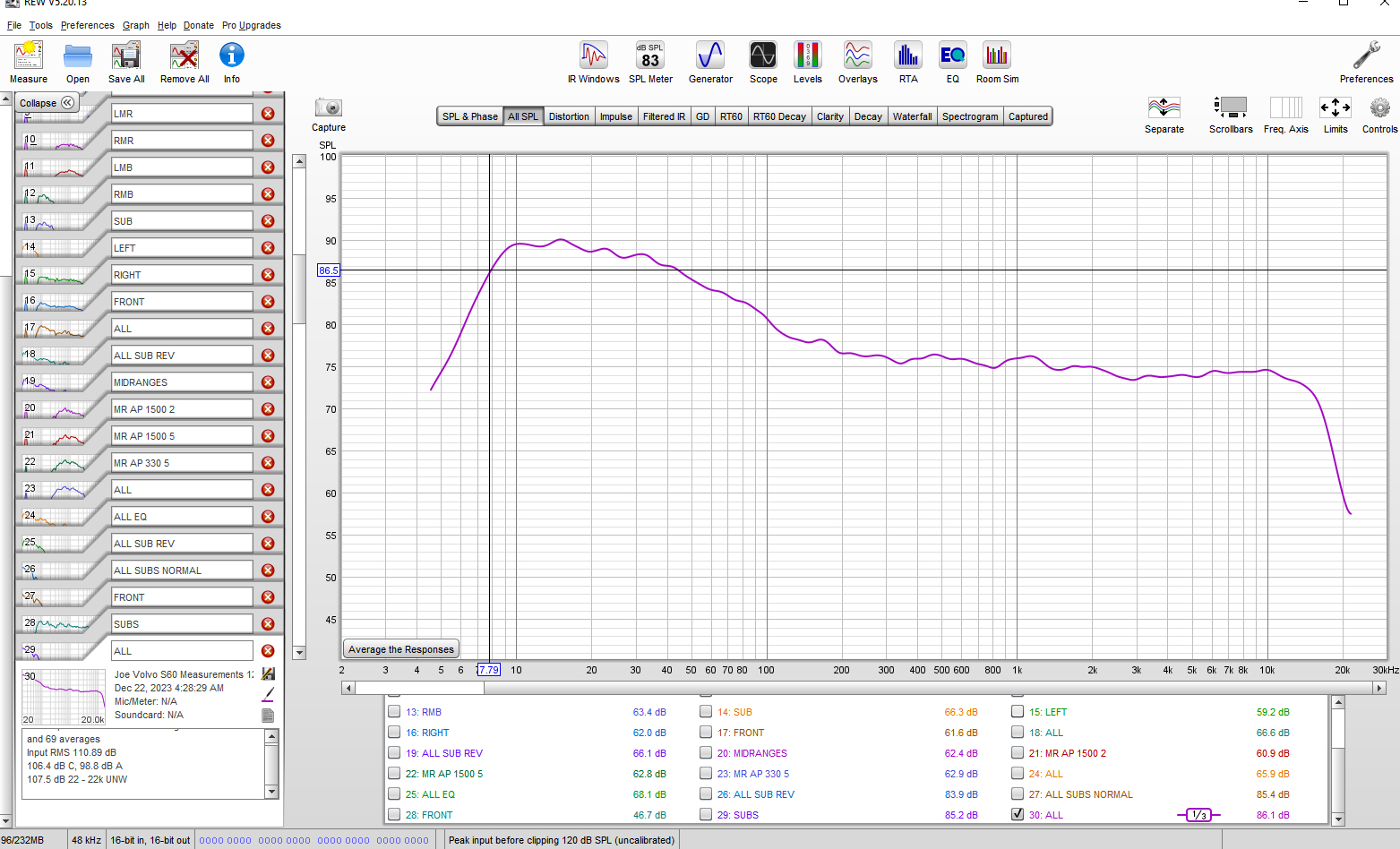
We opted for the P Six over the V Eight since we weren’t doing OEM high-level signal and didn’t need the rear speaker signal for OEM functions such as back-up sensors, and preferred the better amplification and more power to the front speakers instead. In this situation, I think it was the right call, especially since this was a base model OEM system trim and only featured rear speakers in the rear doors and not the rear deck. Short explanation, rear deck speakers are preferred over rear door speakers for rear fill. Going with the P Six Ultimate gave us 230 watts per midbass driver since they are 2-ohm, and obviously plenty of power for the mids and tweeters as well. The Audiomobile Encore subwoofers were wired in parallel to 1-ohm to get the full 1500 watts out of the Helix P One Mk2, and were both placed in their own chambers in a sealed enclosure, with each chamber being 0.9 cubic feet. Sounds tiny, I know, and it is. But my god they handled it excellently. You will see more below. Also note, the Helix P One comes with a very steep 20hz subsonic filter that is set to ON by default. If you want extension below 20hz, you need to remove the back panel and turn this switch off. Read the manual for more information.
To sum up some thoughts before getting into the build log, I am happy to be back to doing things on my own. I think I thrive when I have full and complete control over every square inch of an install. No questioning, second guessing, or wondering. Also no forgetting to pick up the camera and snap some pics. Speaking of which, there are almost 200 of for this relatively simple install. Buckle up.
Before we get into this, it is important to note that every situation is different, every application is different, and everyone’s needs/wants are different. If you would like guidance that is specific to your situation, please do not hesitate to reach out to us.
First up, the doors. Specifically the sound deadening portion. We opted to go with a ResoNix Stage-3 kit for this install since as we all know, “removing” the room from the equation is what separates a good car audio system from a great car audio system. What I mean by this is the more rattles and resonance we hear, the more distortion and coloration it is negatively adding to a system. If a door skin or door panel is moving in any way, it is generating its own sound, which is distortion, and will negatively impact the overall sound quality. It’ll make midbass sound muddy, imaging to be smeared and unable to be fixed, it’ll make the sound stage easily defined to the confines of the car instead of allowing the speakers to disappear, and more, and the only way to correct it is to treat the panels to prevent them from resonating and transmitting their mechanical energy into sound energy.
. ResoNix Mega CLD Squares Sound Deadener (20 Square Feet)
. ResoNix Fiber Mat 45 Automotive Sound Absorber and Decoupler (13.5 Square Feet)
. ResoNix Guardian (6 Square Feet)
. ResoNix Rope (1 Roll)
. ResoNix CCF Strips (1 Pair)
. ResoNix OEM VW/Audi Interior Tape (1 Roll)
. ResoNix Roller
This is what we used to treat the doors in this vehicle, and had excellent results.
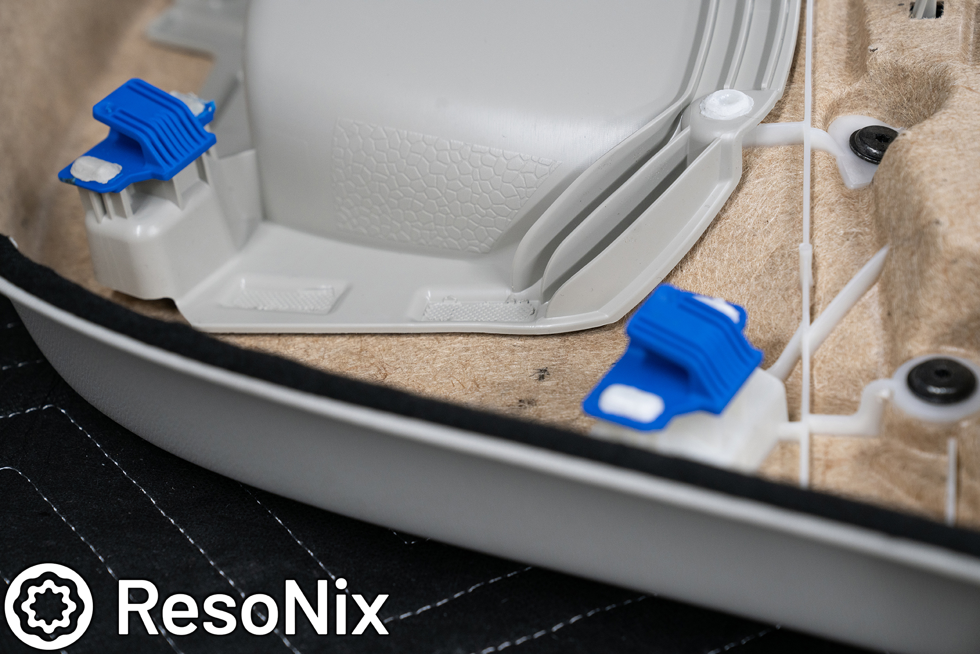
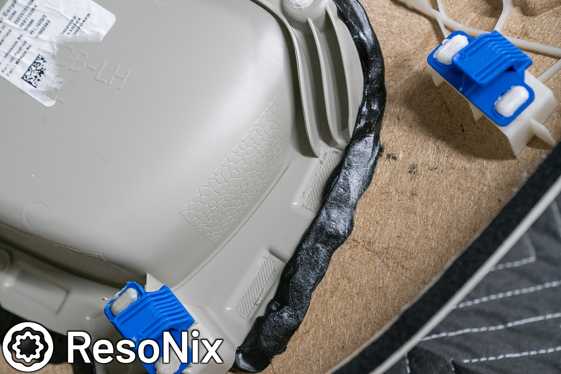
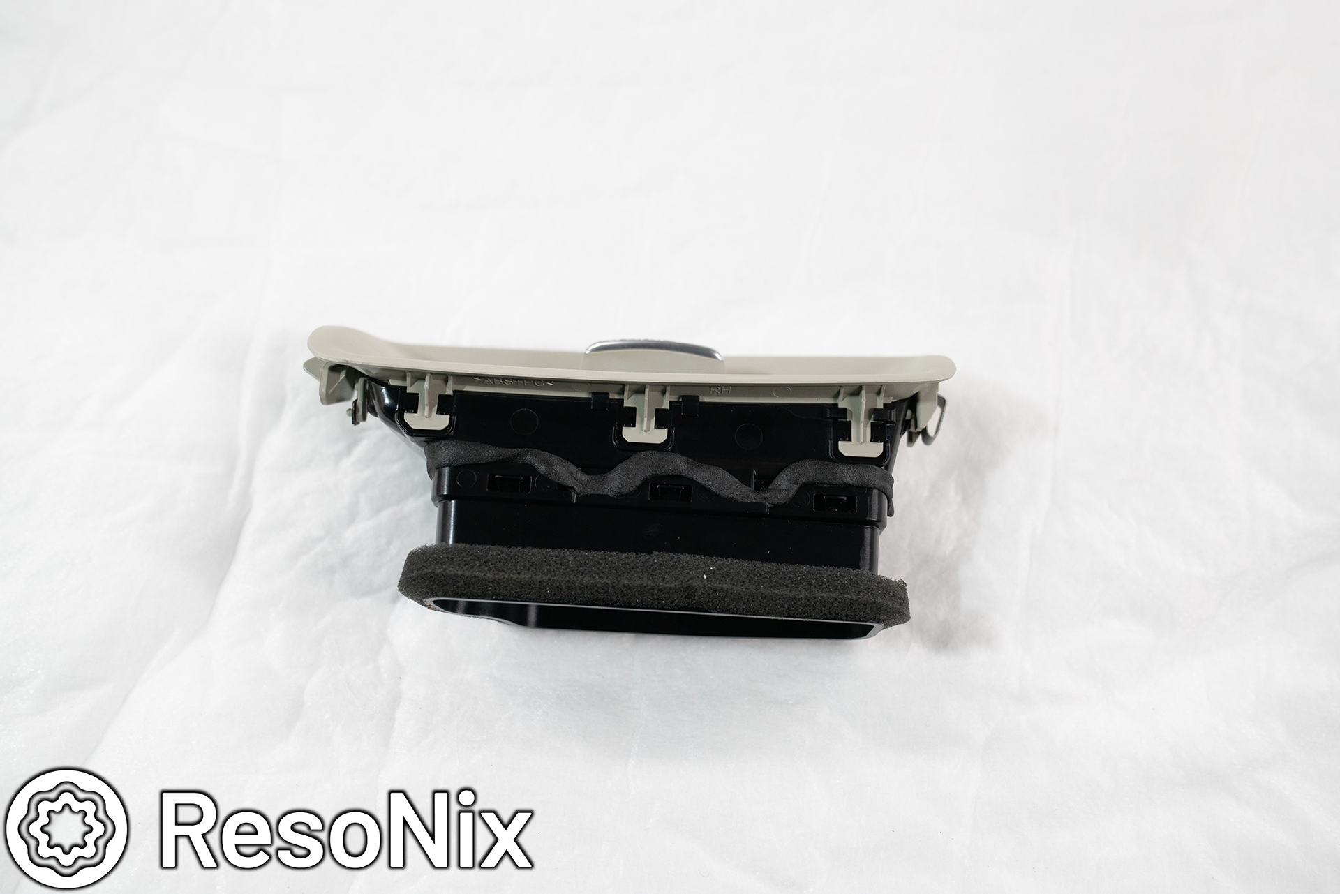
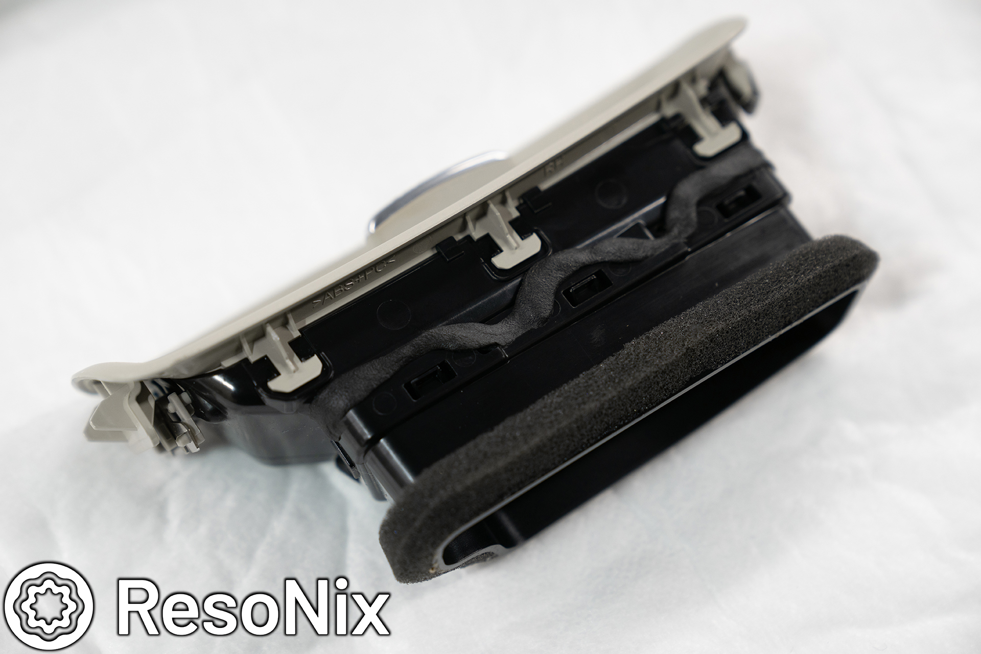
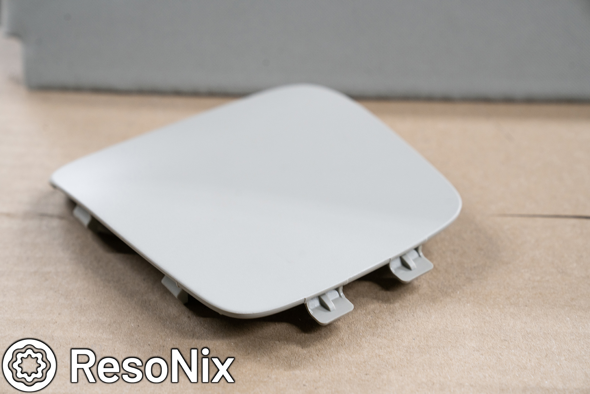
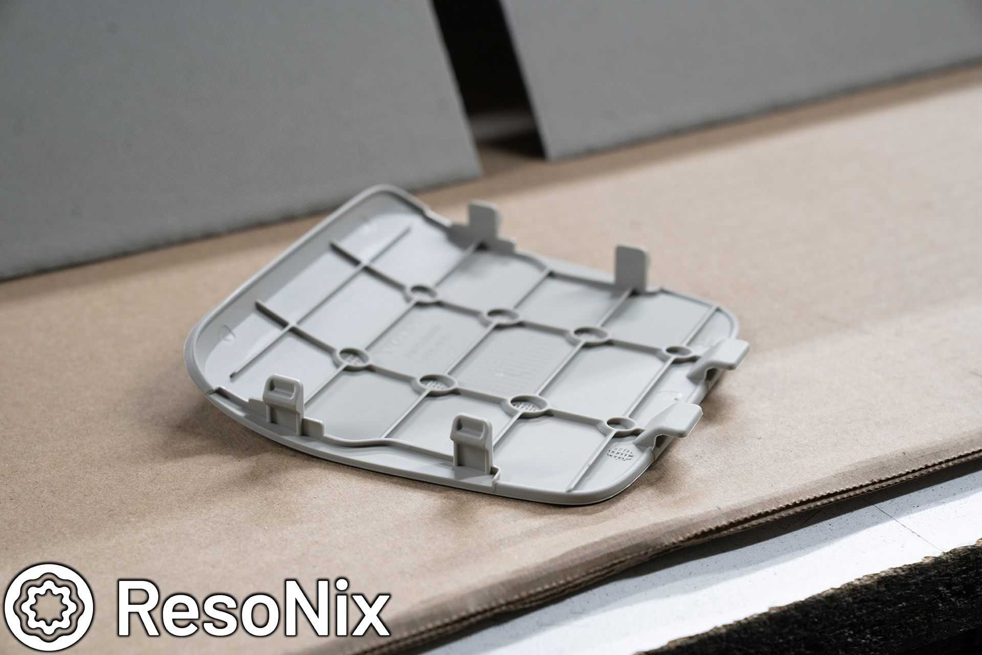
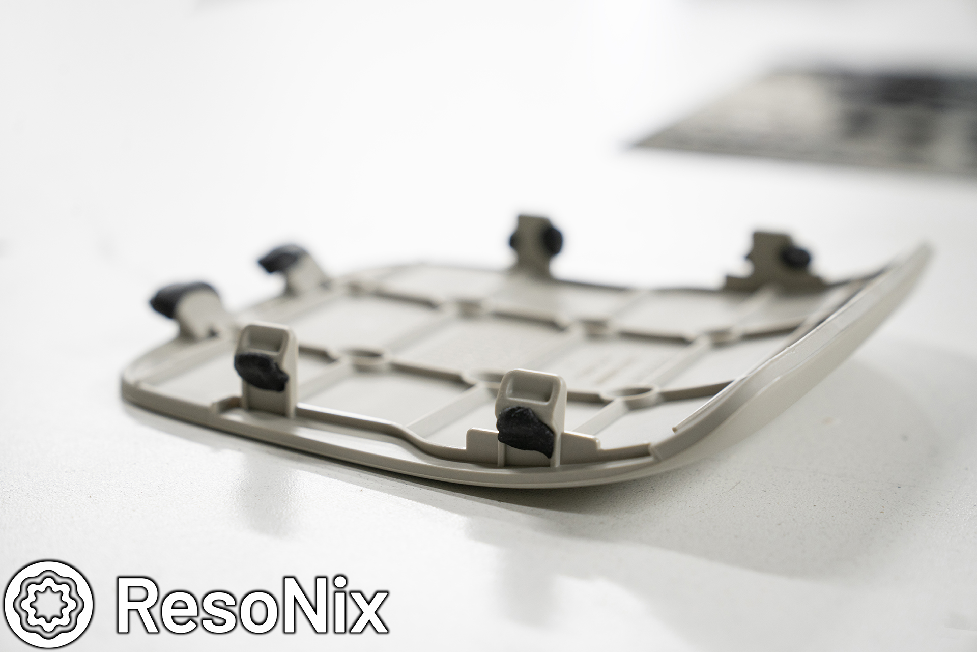
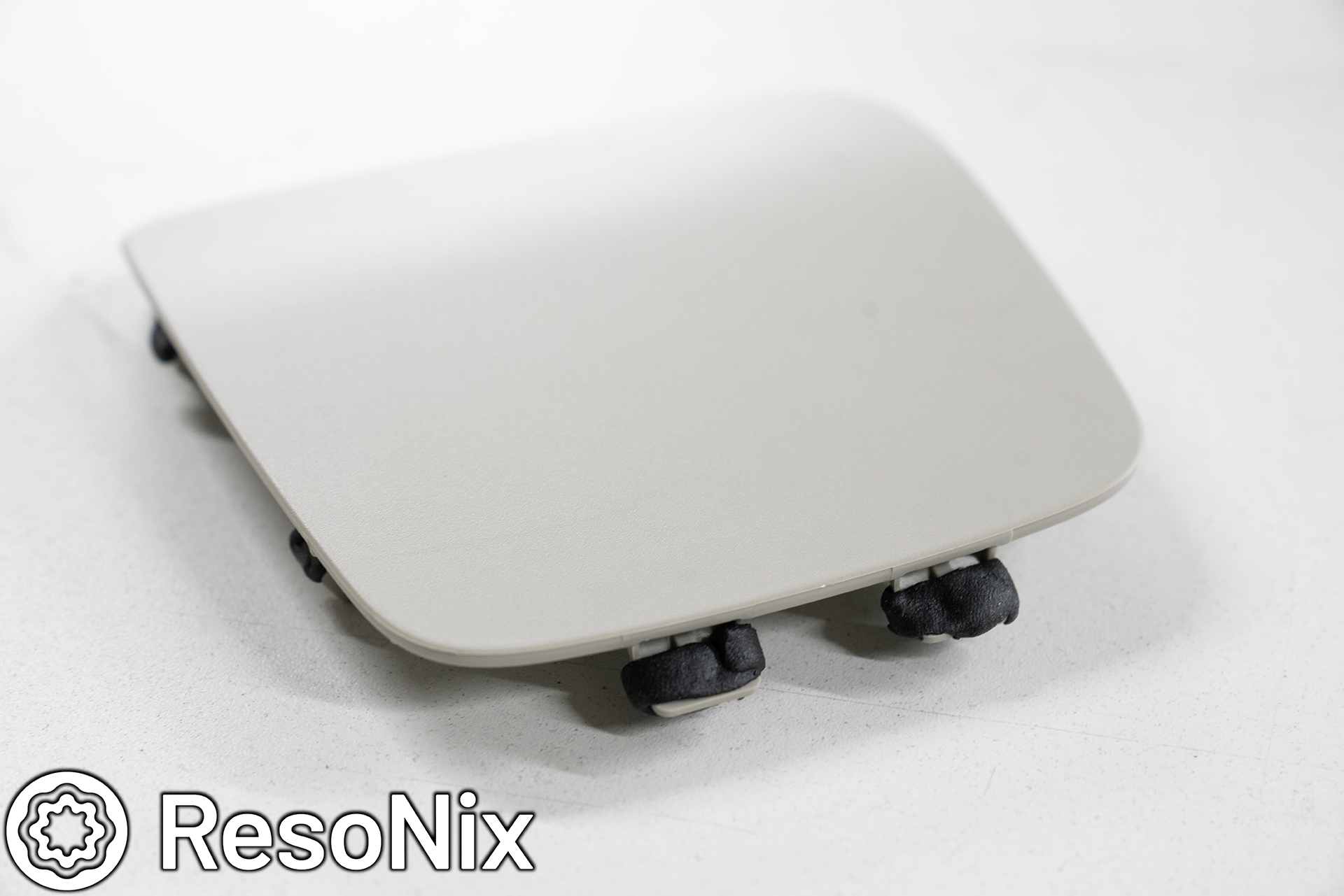
First up, removing the trim panel that covers the OEM midrange and tweeter. This is done by using a very thin pry tool and working your way around the edge. For those with this car, it takes more force than you think, so don’t be afraid to really put some pressure into it. Towards the back, right behind the handle, there is a hook that has to slide out.
Once that cover panel is removed, you can remove the 7mm bolt, and pry up the window switch panel (be careful not to catch the corners on the upholstery), and remove the T25 Torx screw.
On the bottom of the arm rest, you will find an exposed T25 Torx screw. Remove this as well. Once all 3 fasteners are removed, you will want to pull the door panel up and un-hook it from the inner door skin. It does not use push clips, but instead a system of hooks. Once you lift it up, you can pull it right out and it is removed. Once removed, un-clip the wire harness, and un-do the door latch cable.
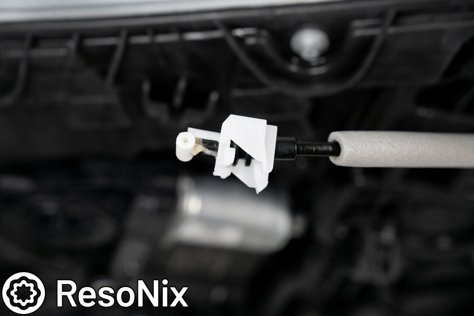
To un-do the door latch cable, you will have to pry off the white cover as pictured here. It will most likely fly off. It is a separate piece and meant to come off of the cable, I just have it pictured on the cable here to show you how it is supposed to be positioned for re-installing.
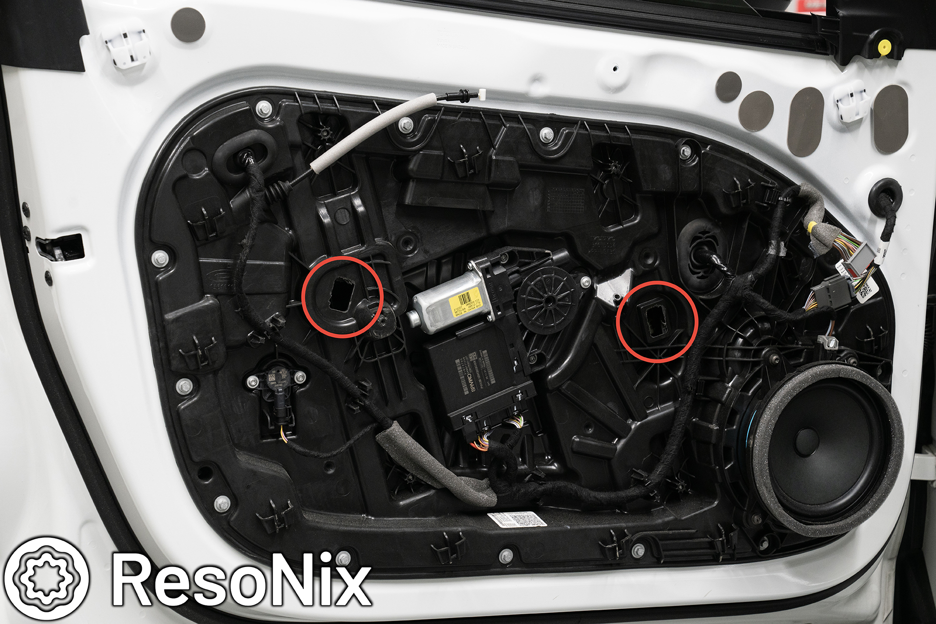
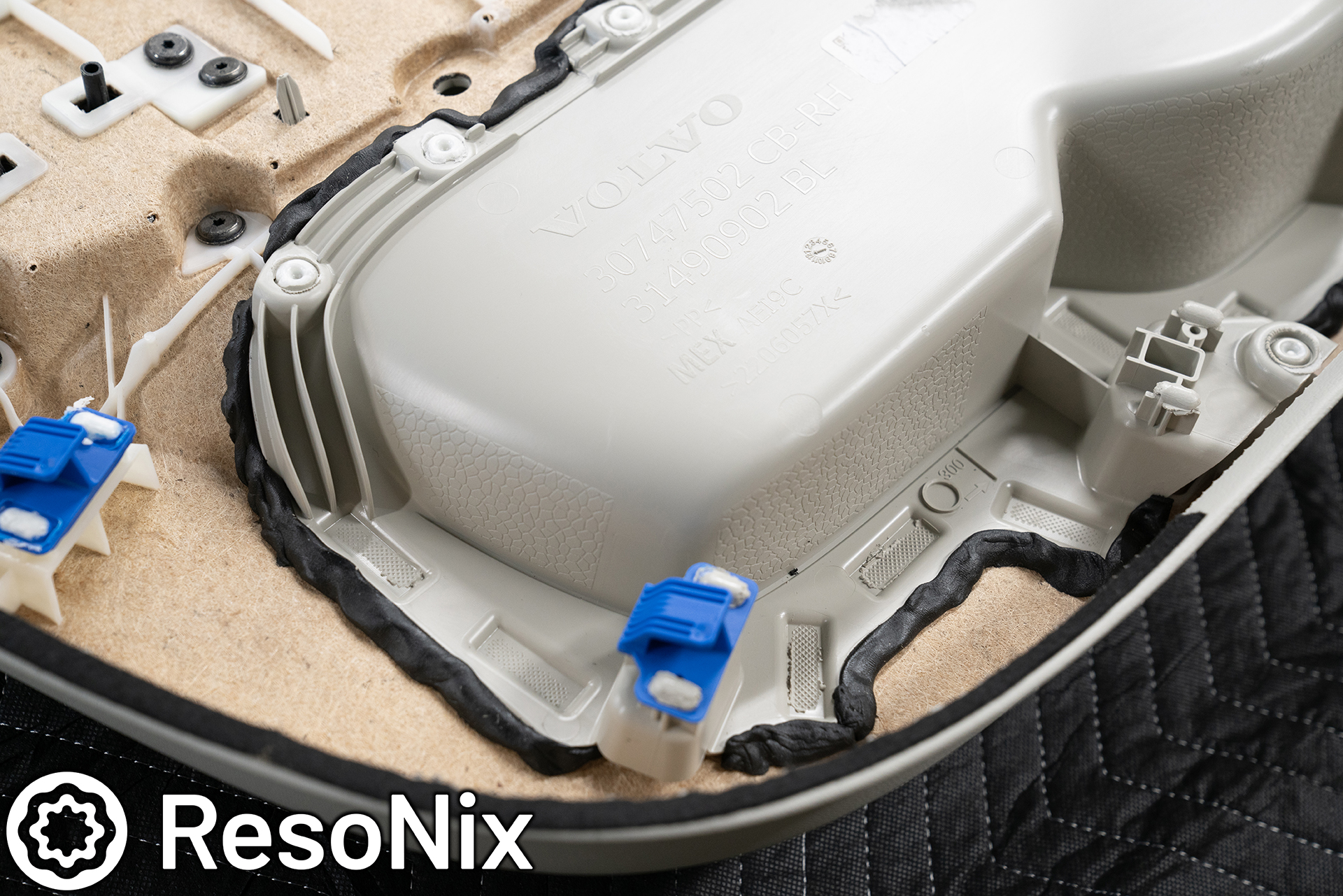
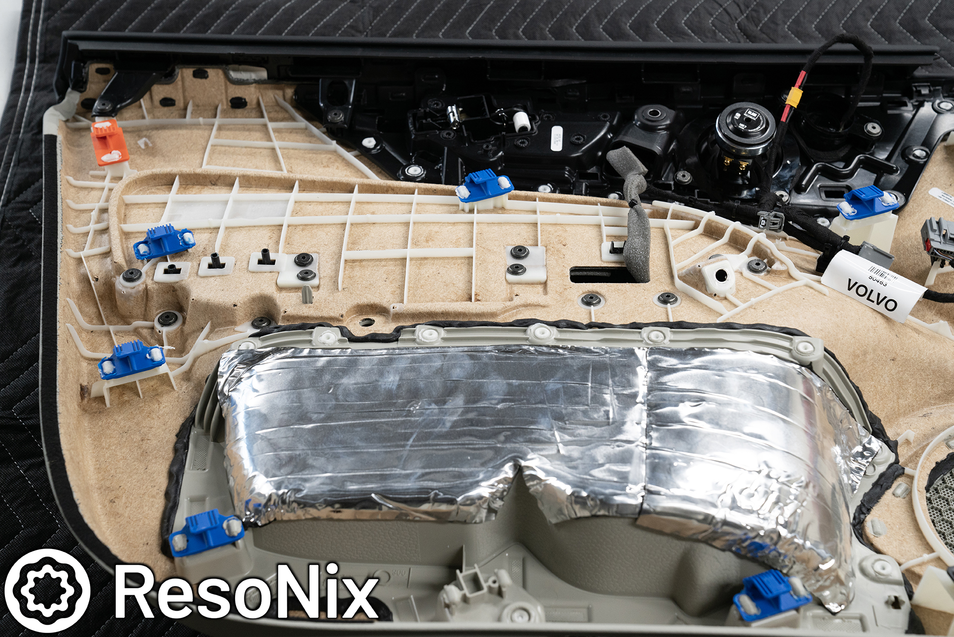
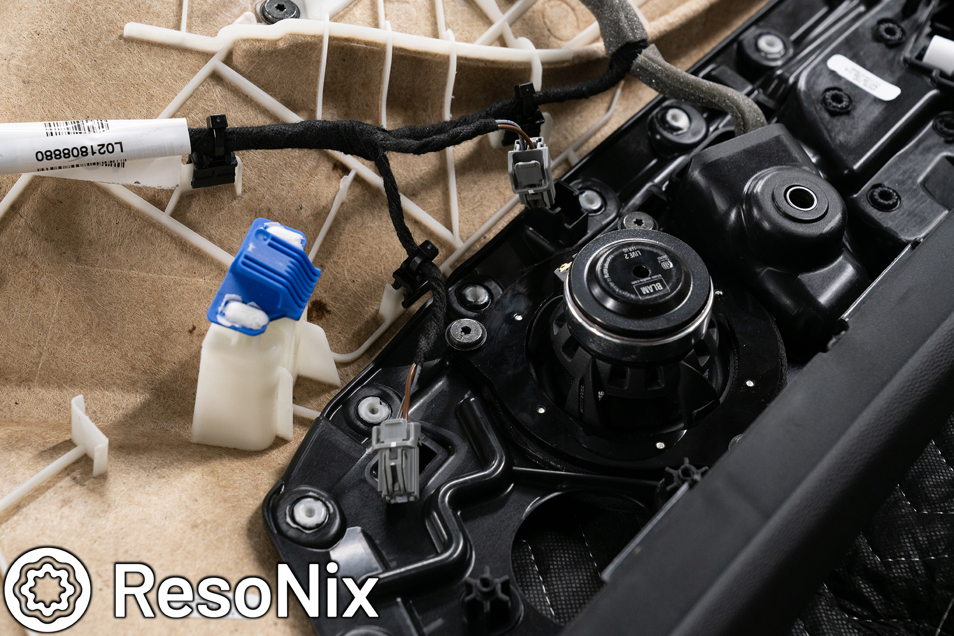
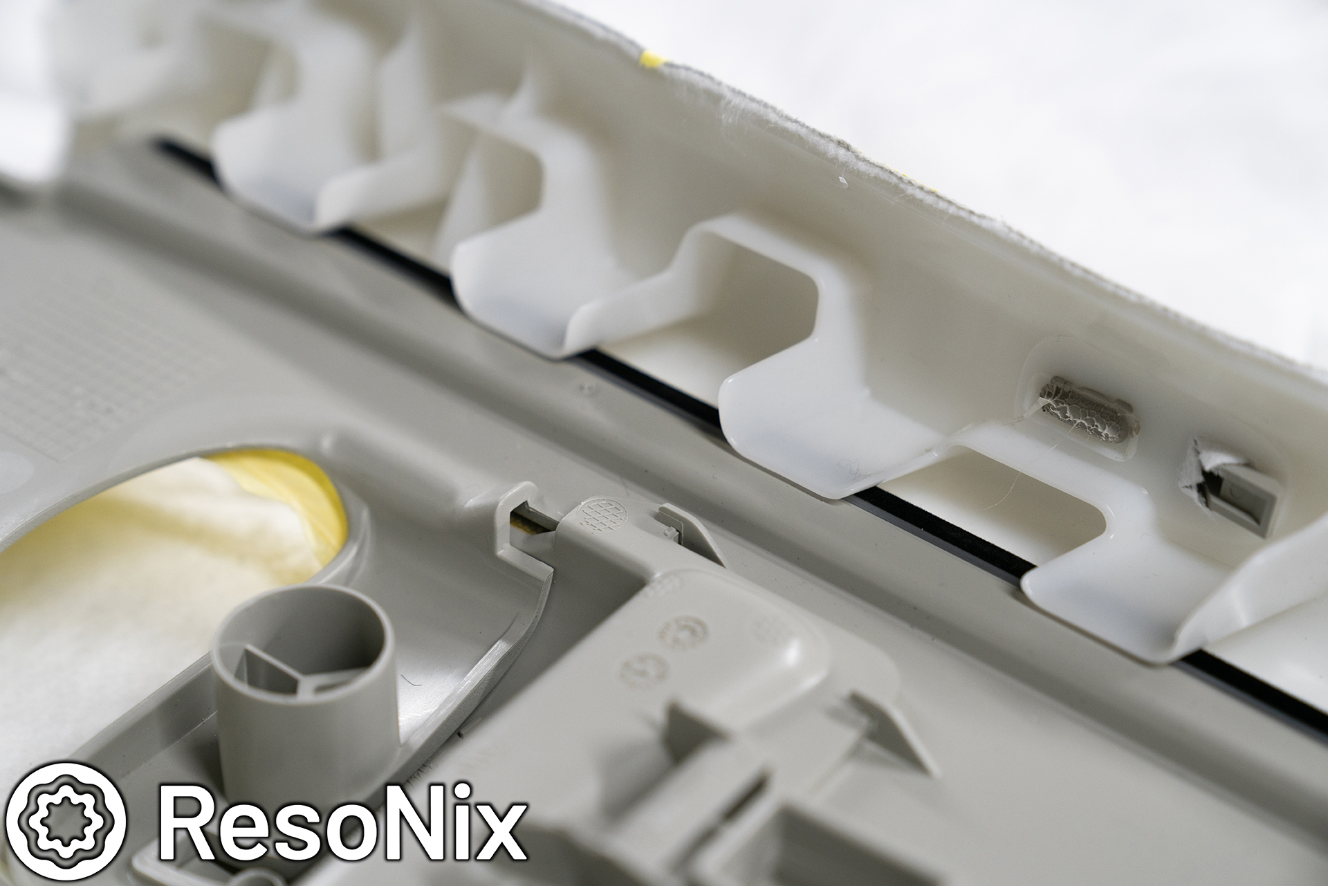
Once the door panel is off, you will be greeted by this sight, the inner door skin and its large access panel. Having worked on a few of these vehicles now, it seems there are a few different variations of one method to get this access panel removed from the inner door skin for this generation of Volvos. In any variation, you will need to remove the window, the exterior door handle, and the door latch.
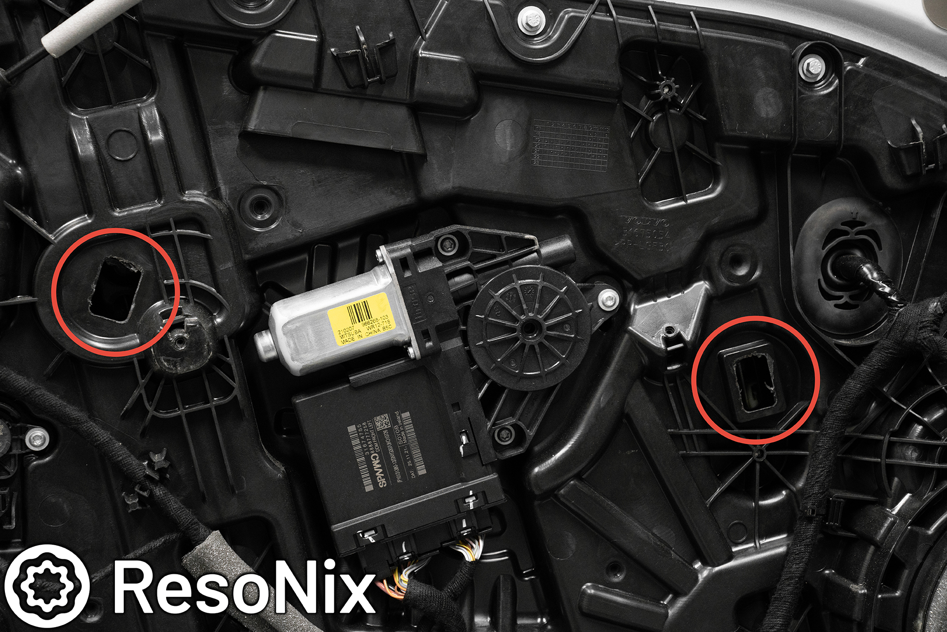
In this case, the Volvo documentation shows that in order to access the clips that hold in the window, you literally have to chisel out two parts of the inner door skin, circled in red. Yes, chisel. Why they didn’t use a removable grommet like in some variations, I have no idea. Pictured here they are already removed, but if you have the same variation, all you will see is two plastic squares that are just a part of the access panel. Not separate pieces. These need to be chiseled off with a chisel and a hammer. I really could not believe what I was reading, but if you are reading this and want the OEM documentation to do your Volvo, feel free to email me.
The next step is to get the window rolled down to a specific depth (190mm from top of window to the top of the black window trim (if you need to more specifics, again, feel free to email me and I can send it to you). Once it is rolled down to the right height, At the right height, you will see two circles in the glass when looking through the holes you chiseled out. In those circles, a plastic clip hooks in. You will insert a screwdriver into the openings that you created, and through the circle of the glass, and push open the hook while pulling up on the window. Repeat with the second opening. From there, slide the window out completely and set off to the side.
The next and possibly most difficult part depending on the trim you have, the exterior door handles. This was a bizarre one for this car, as the driver side had them held in with a screw, and the passenger side had it held in with a latch. The screw version is MUCH easier to remove and reinstall. You can see how that is done in this link to an S90 installation that I did in the past. For the latch style, I watched every single YouTube video and read every bit of documentation, and even reached out to some Volvo techs. It still didn’t make sense to me, but in the end, I was able to remove and reinstall the passenger side one of this car without issue.
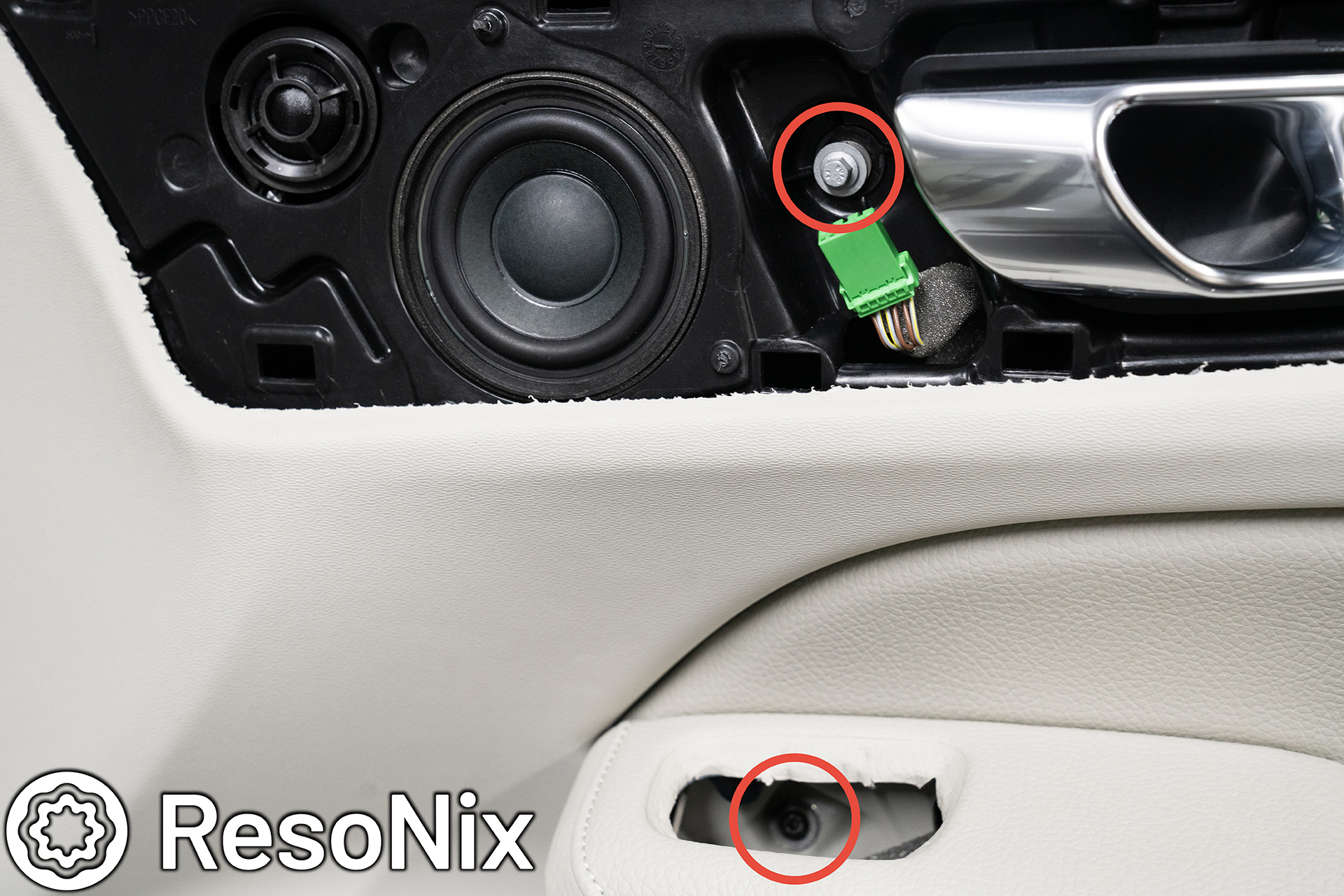
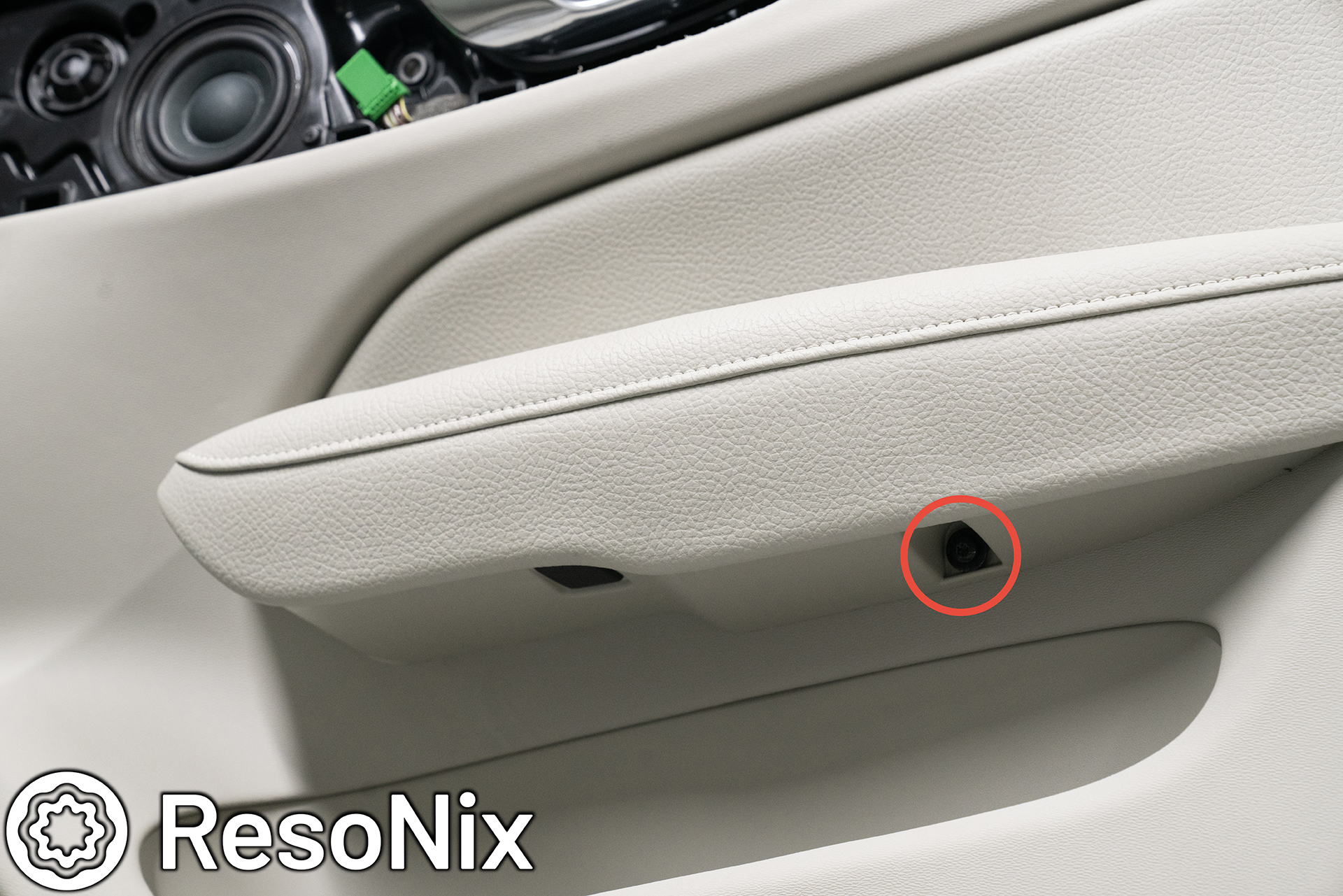
Once the handle is removed, remove the screw that is behind it, and remove the 3 screws that hold on the door latch. Once those are removed, you can remove all of the 7mm bolts that surround the outer perimeter of the access panel, and remove it. I would also suggest removing the door wire harness Molex plug from the door jam, and remove this entirely, which you can do easily. I will explain in photos below.
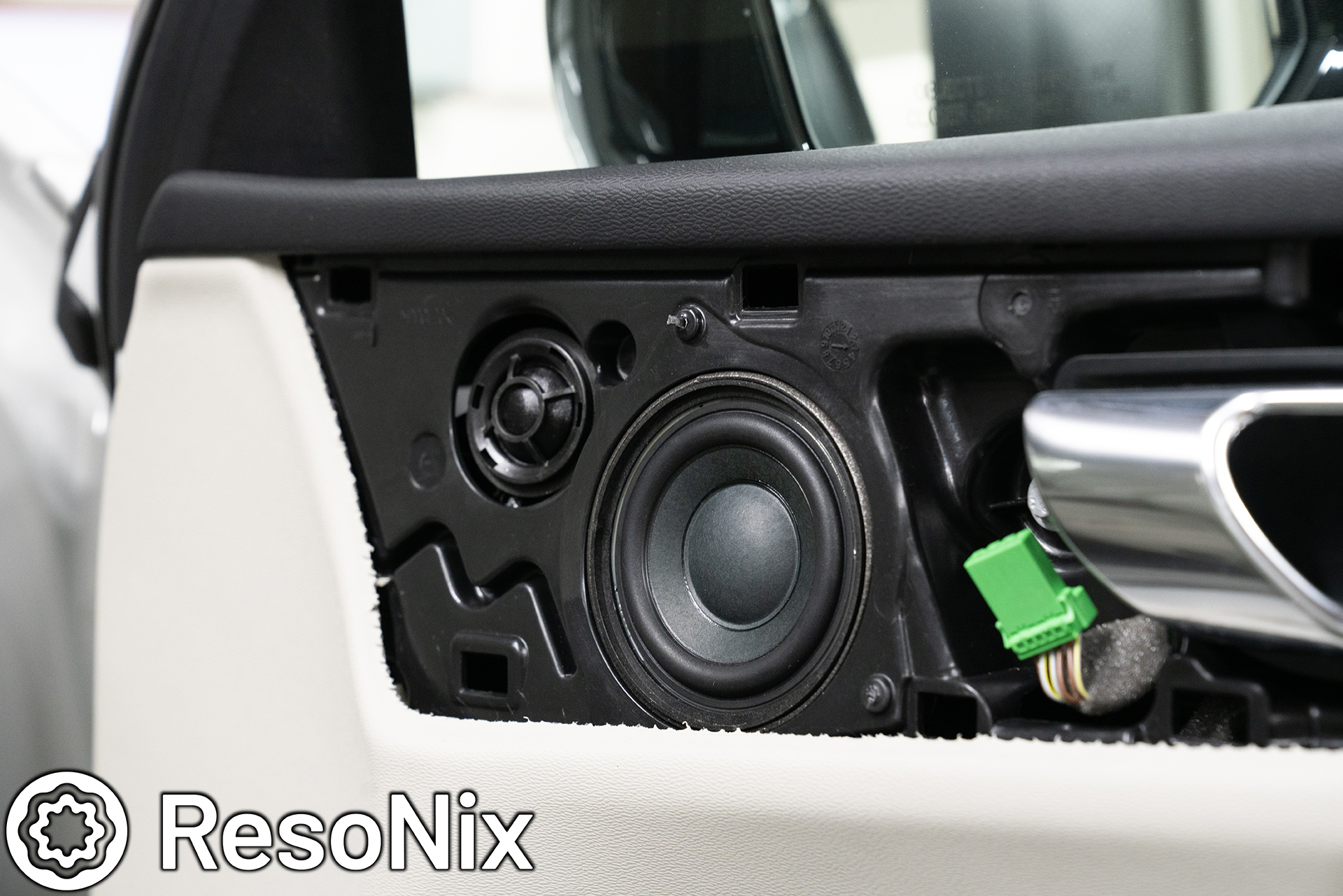
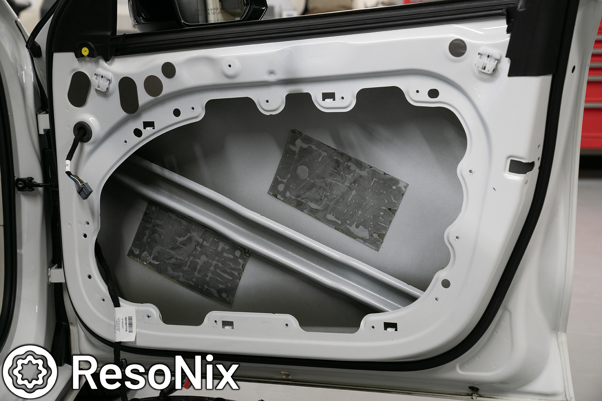
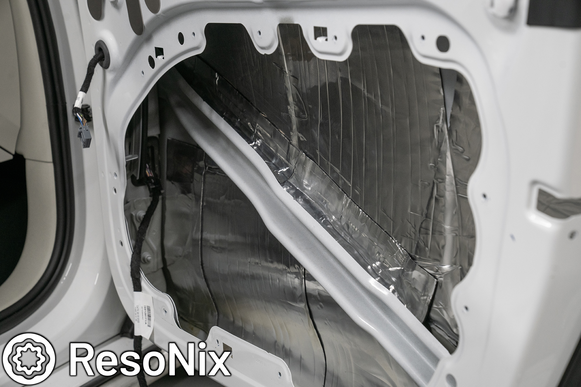
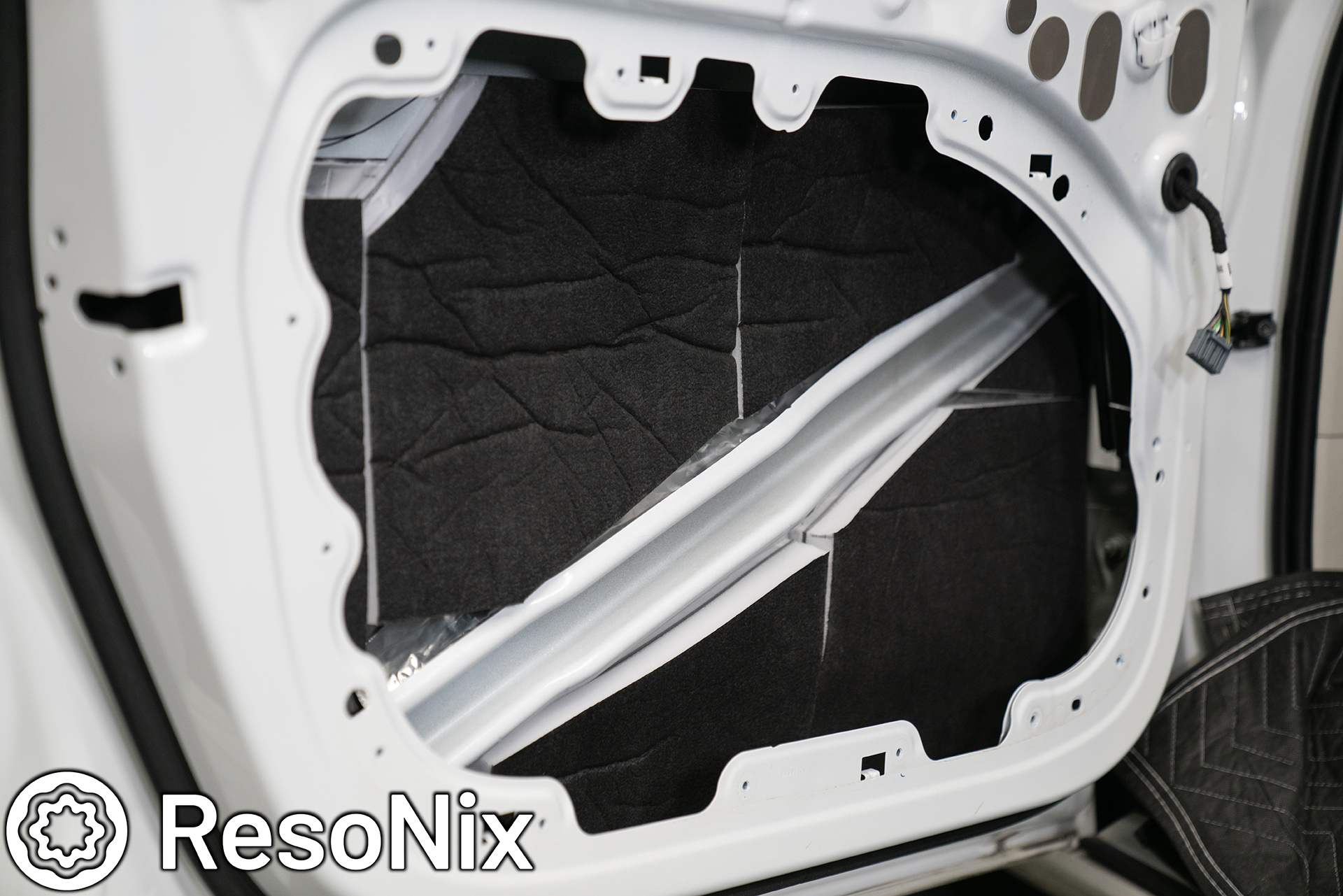
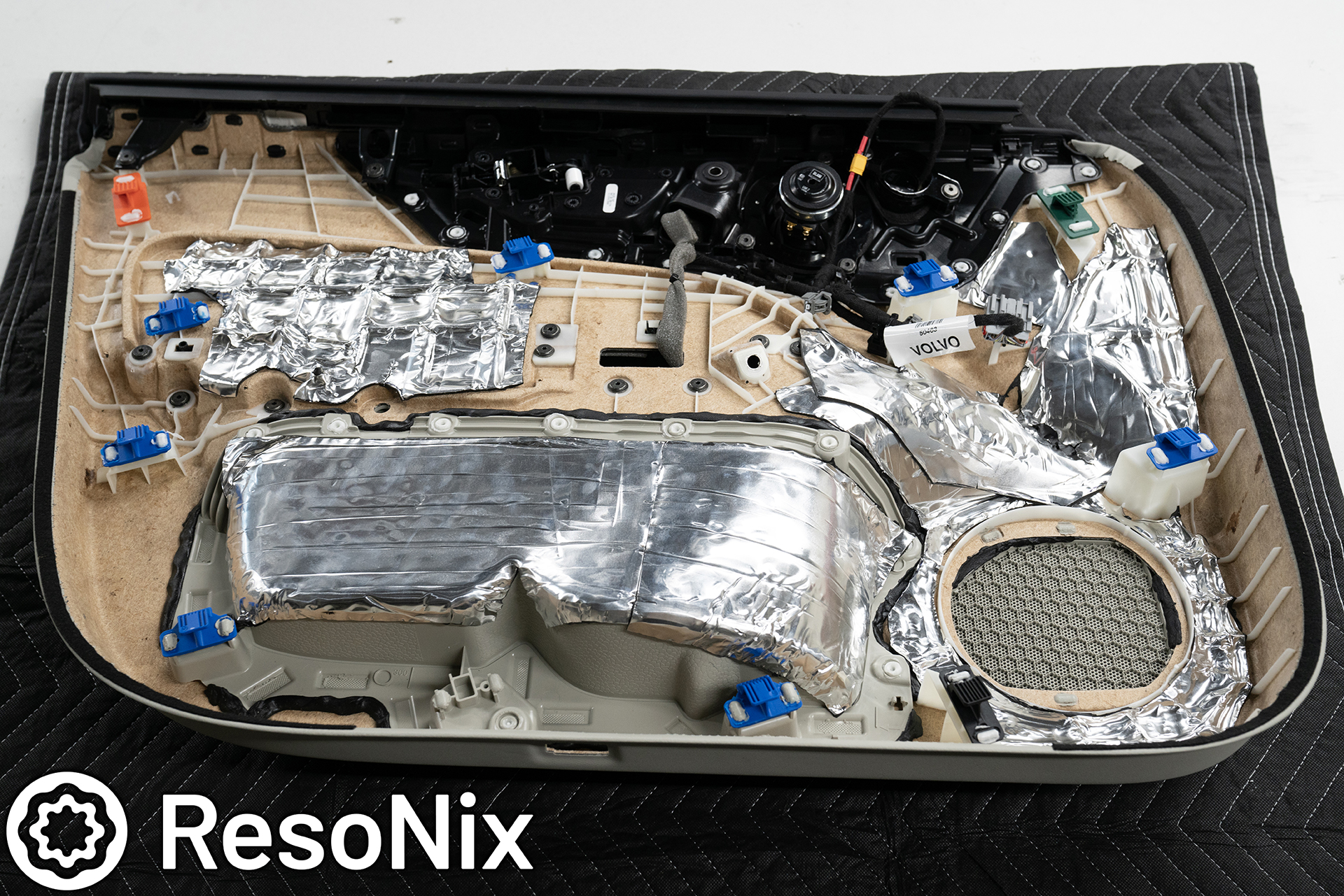
Once that is all removed, we have a TON of room to work with to sound deaden the outer door skin. And look at that, Volvo was nice enough to include plenty of their own deadening….. which is extremely poor in performance. The first thing that I did was remove it, which was surprisingly easy. The butyl seemed to have absolutely no viscoelastic properties, which may explain its very poor performance.
Once the two sheets that were installed from the factory were removed, I cleaned the outer skin with isopropyl alcohol to make sure all dirt, grease, oil, and grime was removed. The only place that I DIDNT clean was at the very bottom of the door, and this was on purpose. This area had some very thick grease applied, for what I could only assume is for corrosion prevention. I left this in place and did not install deadener over it.
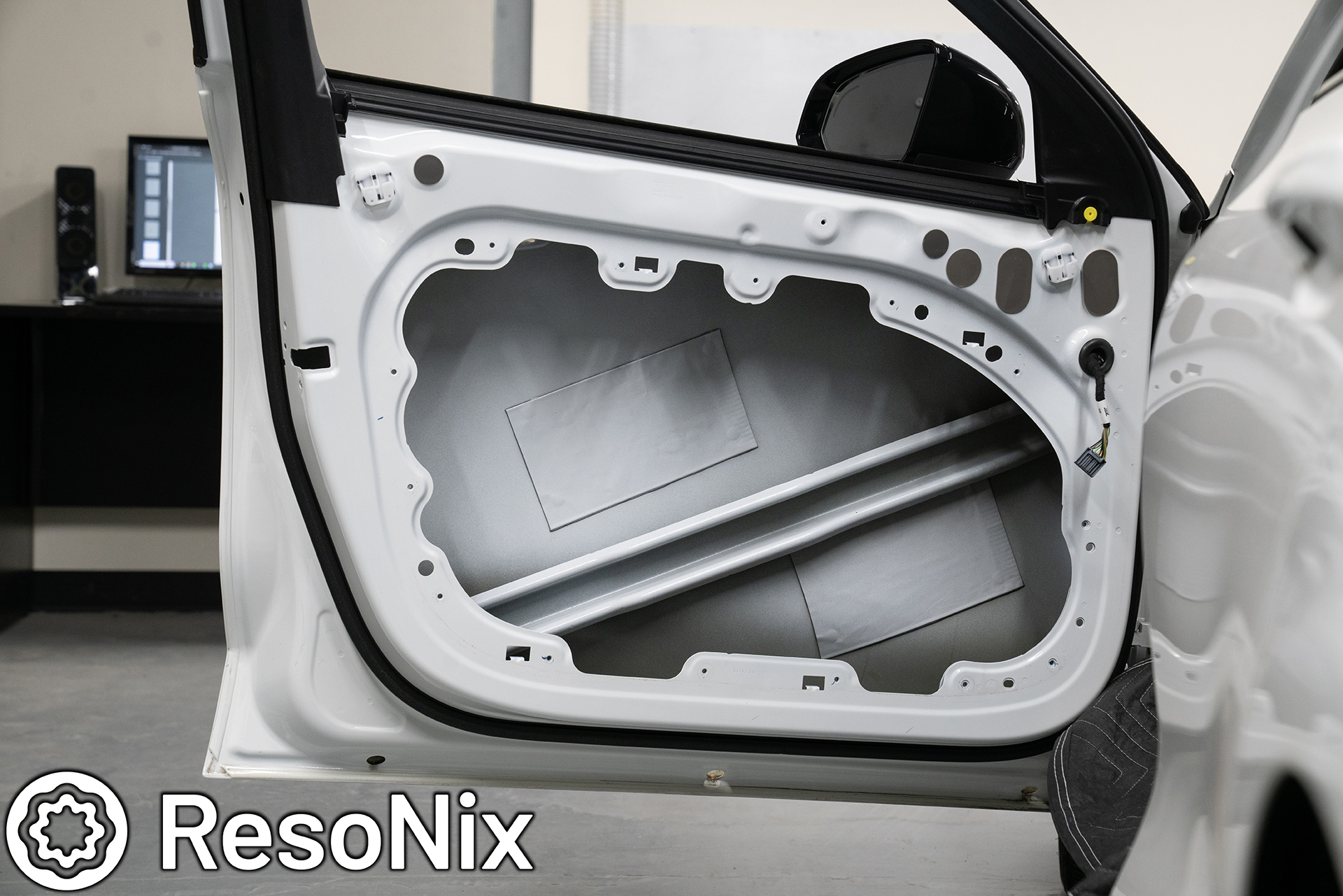
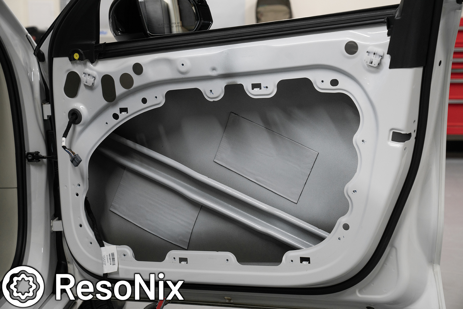
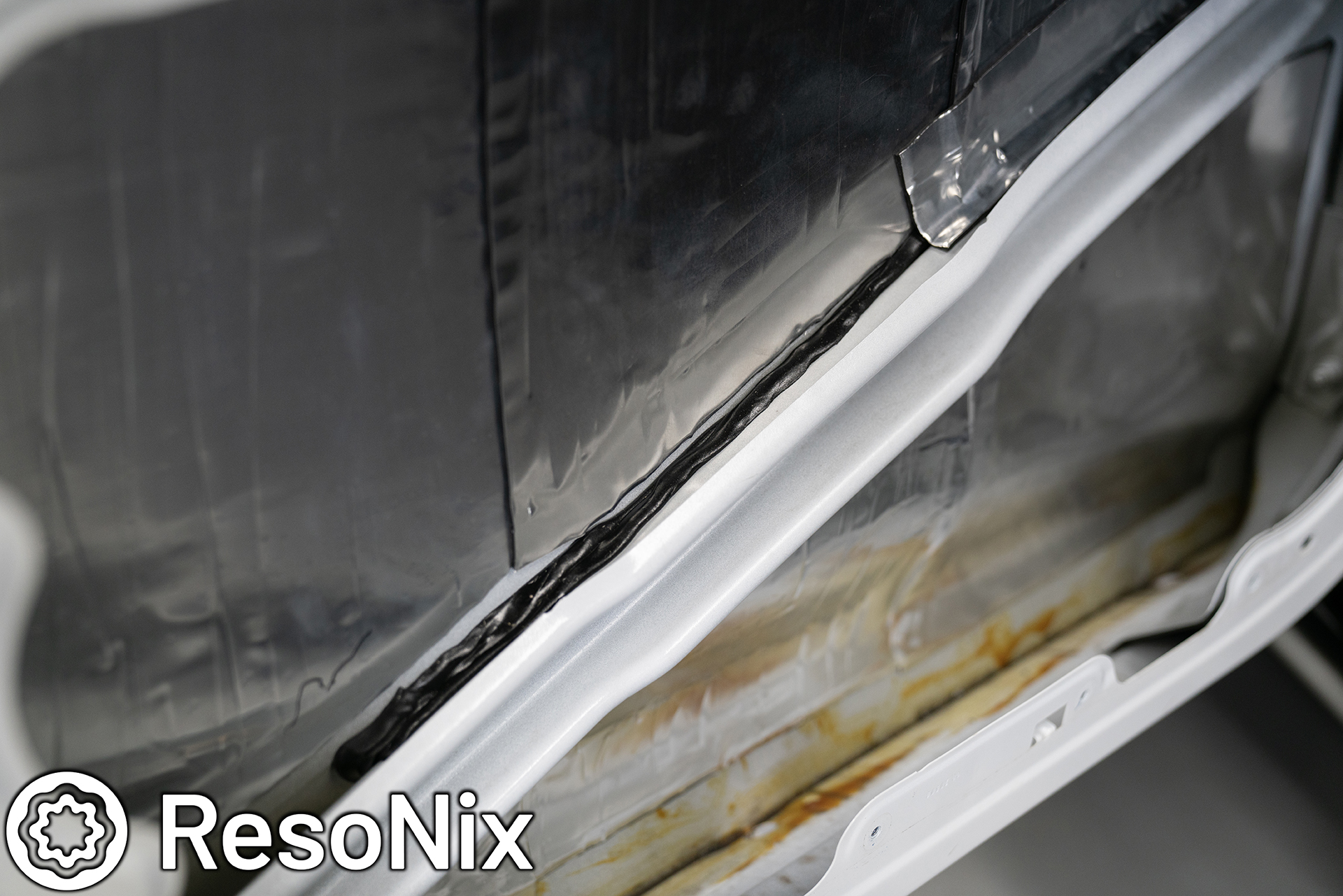
Once the door was cleaned, I was ready for the first steps of sound deadening the door – treating the outer skin. This starts with using ResoNix Rope in between the crash bar and outer door skin, and then doing strips cut from ResoNix Mega CLD Squares deadening from the crash bar to the outer skin, and then doing full coverage of the Mega CLD Squares on the outer skin. The only place that I didn’t cover is the area where the exterior door handle secures. I did not want to get in the way of it and cause any issues.
Some may ask why and scoff at doing full coverage saying it is a waste. I say that is silly, and not true. 2 reasons why. First, the “25% rule” that a lot of people like to throw out doesn’t exist. Constrained Layer Dampers do not know how large a panel is that they are adhered to, and do not know how large their piece is. The way constrained layer damper works is by constraining the panel it is adhered to. Any of the area left without treatment, essentially becomes a new, separate untreated panel. Let me provide an example. Lets take an SUV’s roof skin, and a small vehicles outer door skin. A large SUV’s roof skin is going to be somewhere in the ballpark of 10 feet long by 6 feet wide. 60 Square feet. A small car doors outer skin will be, at most, 3 feet by 2 feet, 6 Square feet. Doing 25% coverage of the outer door skin would yield an untreated area of 4.5 Square feet. Doing 25% coverage of the 60 square foot roof skin would yield an untreated area of 45 square feet. Now let me as you, if you saw 45 square feet worth of untreated flat surfaces, would you leave them alone? Absolutely not. Think of applying CLD as if you are just taking away part of the panel from the equation, but it does not constrain the areas it does not cover. Those untreated areas now become their own untreated panels. Now, if you HAD to do only 25% coverage, you could be VERY meticulous and figure out a very strategic way to place each piece in a way that leaves a “maze” of untreated panels that varies in differing sizes to change up resonance patterns, but things brings me to my second point…. I value my time, and I greatly value the end result. If it takes a few extra bucks worth of material to not have to sit there and waste time figuring out the most efficient way to apply it, and doesn’t leave me second guessing if I did enough, especially on the most important part of the install, it’s worth it to me. Anyone doing a build worth while in a modern vehicle is already spending a large chunk of change to do it correctly, and skimping on arguably one of the most important parts to save a few bucks just doesn’t make sense to me. But hey, call me biased 🙂
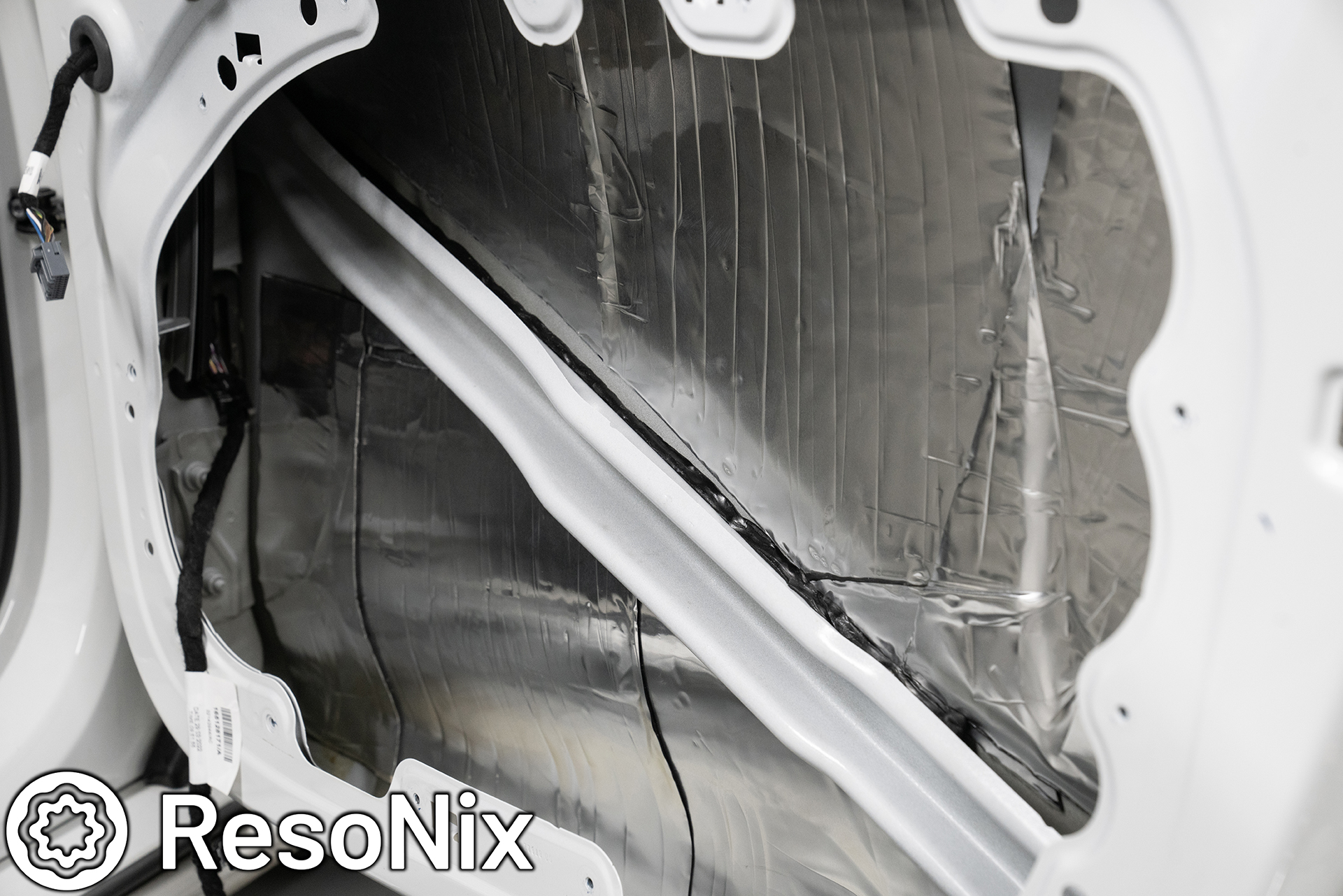
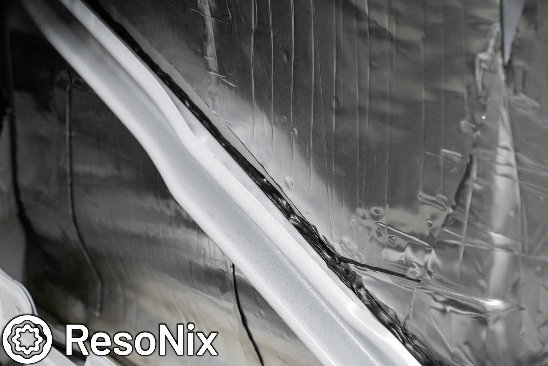
Here you can see the ResoNix Rope that is stuffed in between the crash bar and the outer skin. I did this on the top and the bottom. I would also normally provide some gaps for water to drip through, but Volvo already had this fully sealed up with foam adhesive, so I just ran it the whole length. I normally would have done this first and then done the CLD over that connecting the crash bar and the outer skin first before doing the outer skin CLD treatment, but frankly, I forgot to do that order due to being excited to get to use the ResoNix Super Max Mega Pro CLD Squares for the first time in a customers car. I ended up doing the connecting strip after, which is still fine, but in theory would be a hair better if I did it first. We are talking insanely miniscule differences here.
Here you can see where I start to install the “connecting strip”. Again, this is to help further couple the crash bar to the outer door skin, and use the strength and rigidity of the crash bar to further stabilize the outer door skin. You can also see the grease at the bottom that I left. Considering there was so much, I figured it must be there on purpose, and I did not want to ruin the integrity of the vehicle.
I also ran the ResoNix Rope along the bottom gap between the crash bar and outer skin.
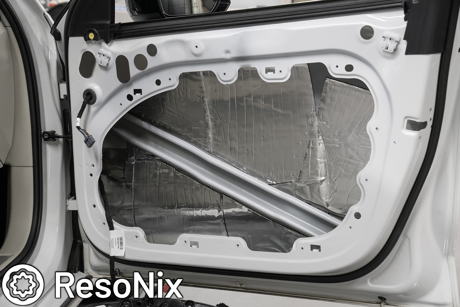
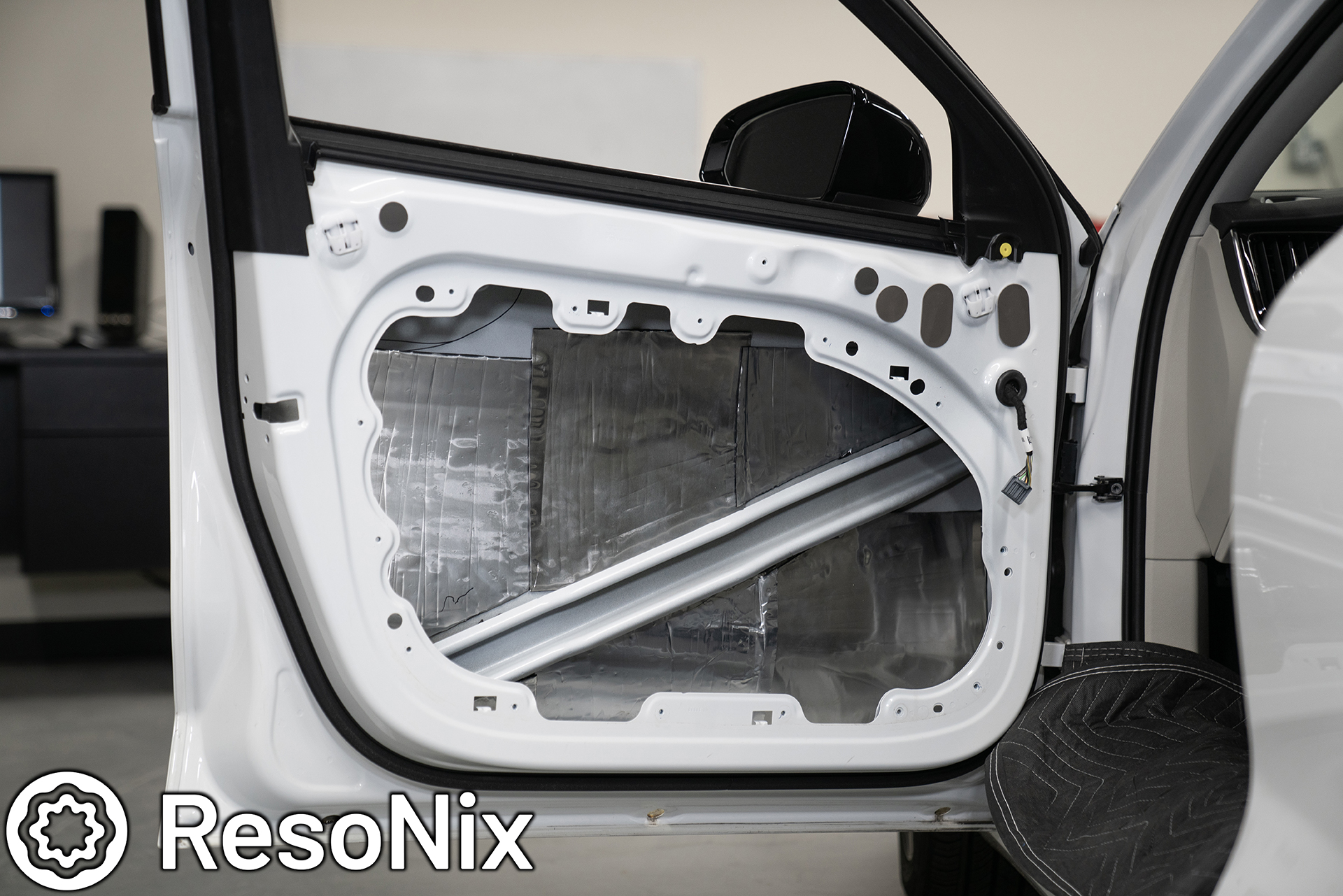
After this, you can see the whole outer door skin CLD and Rope treatment completed.
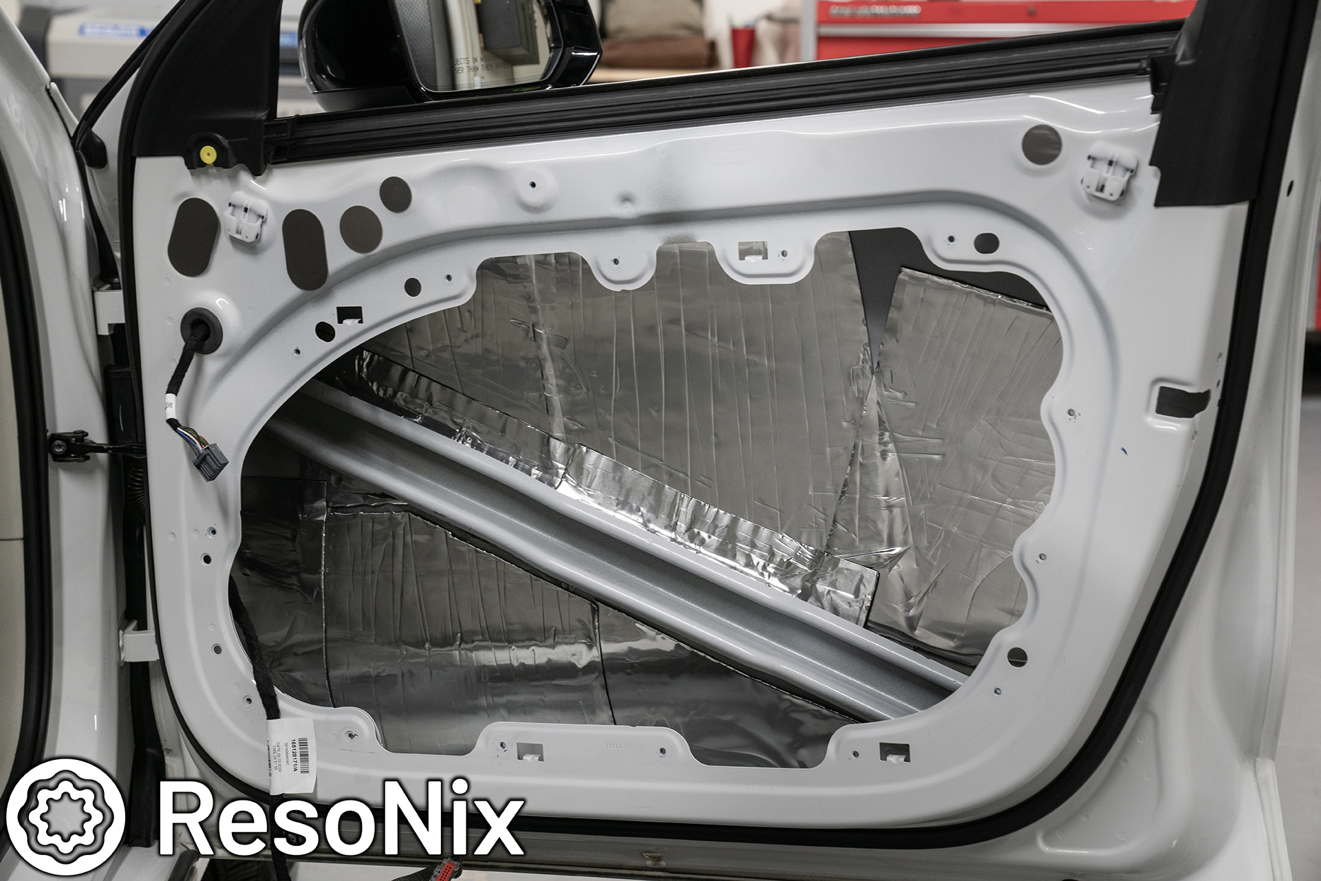
Up next was the ResoNix Guardian installation. I used all 6 square feet split between the two doors. With CLD sound deadening products, you get the best performance by leaving them in as large of pieces as possible. This is not really the case with sound absorbers such as ResoNix Guardian. The only reason I kept the pieces this large was because I had such a large opening to work with and it was easy. If I had a vehicle that had smaller access holes, I would be cutting it into smaller pieces that are easier to work with.

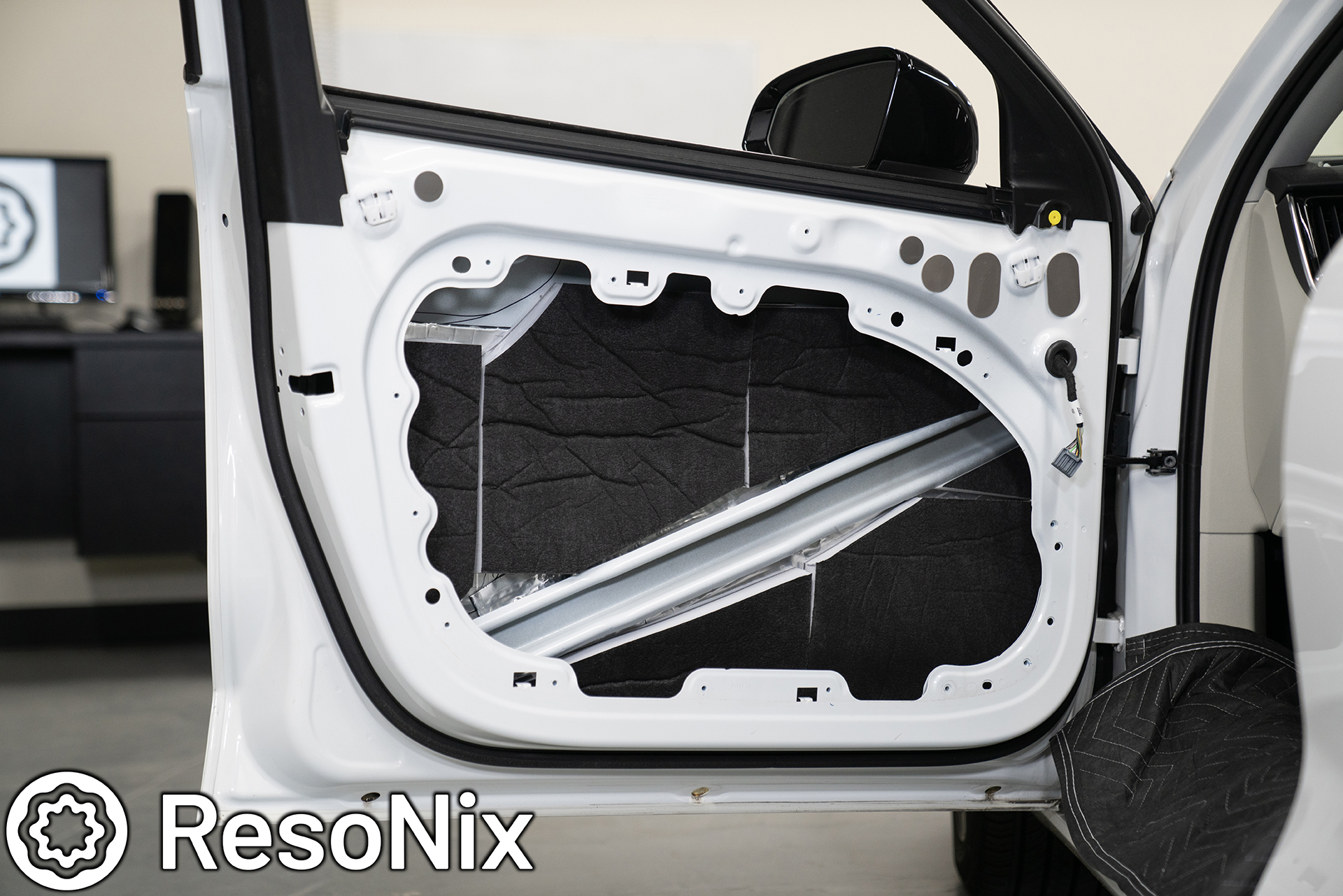
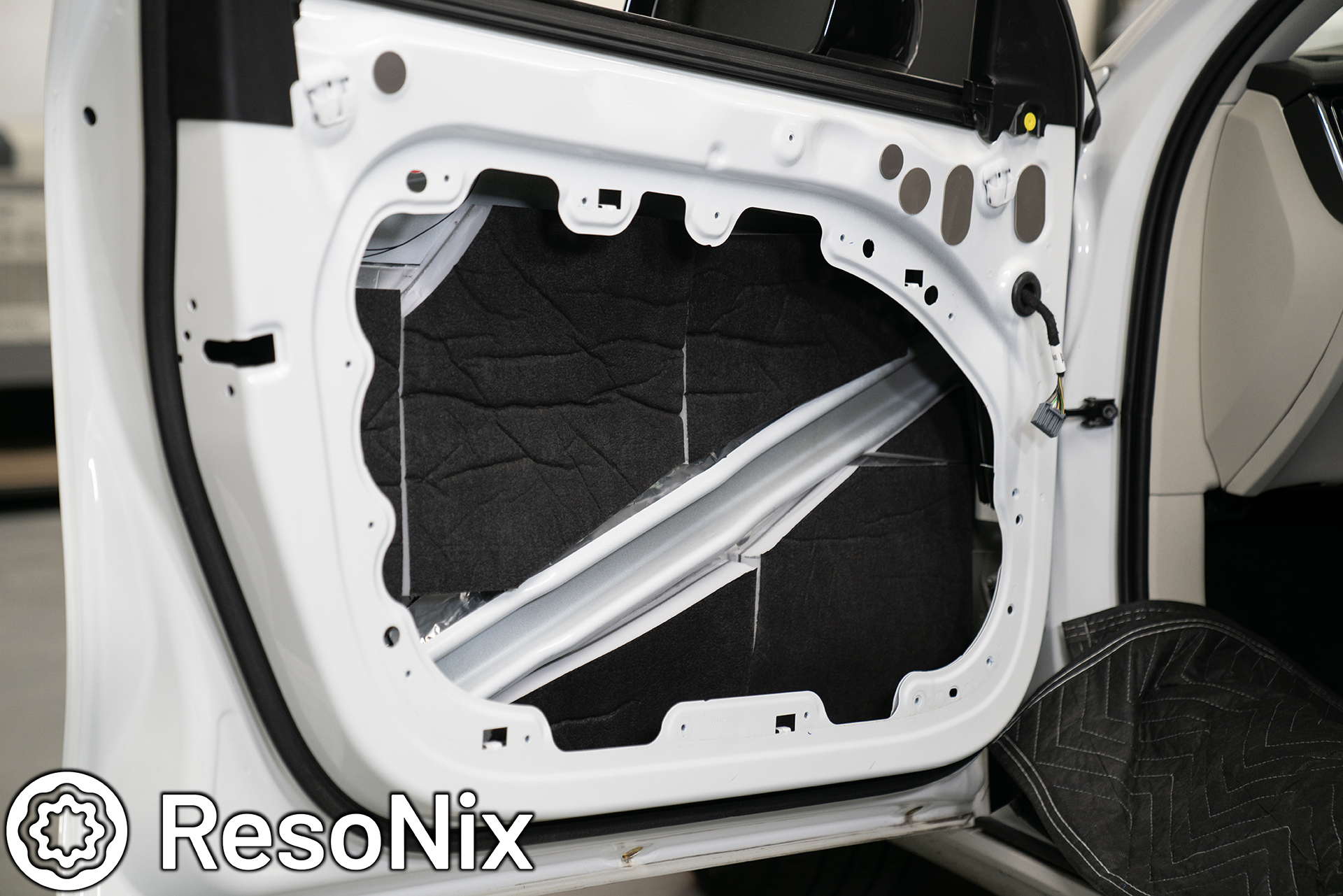
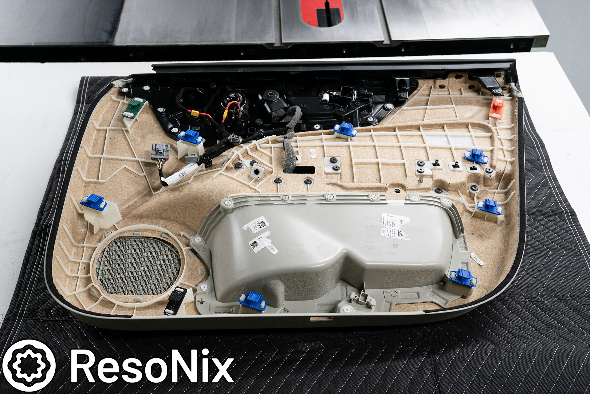
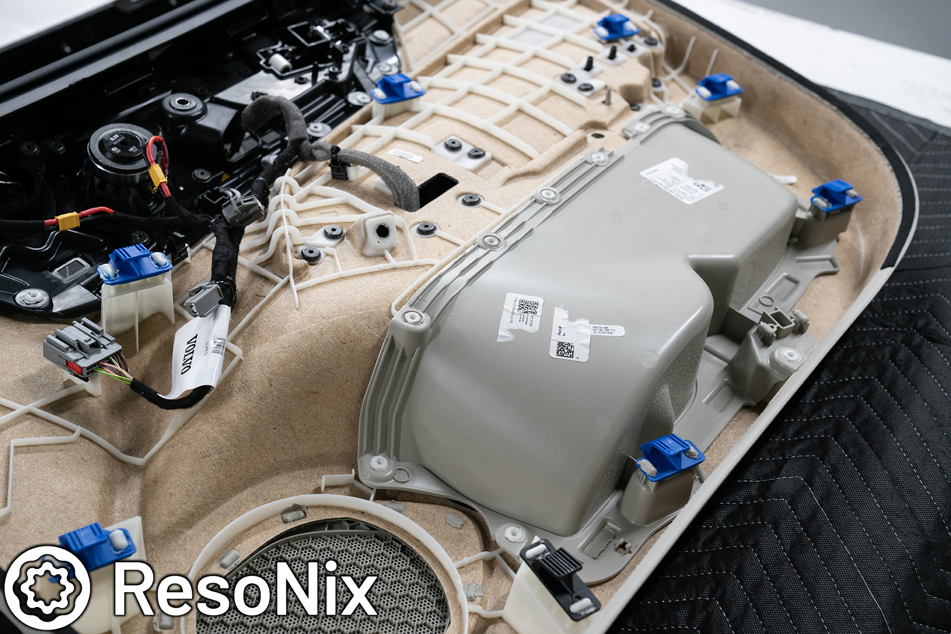
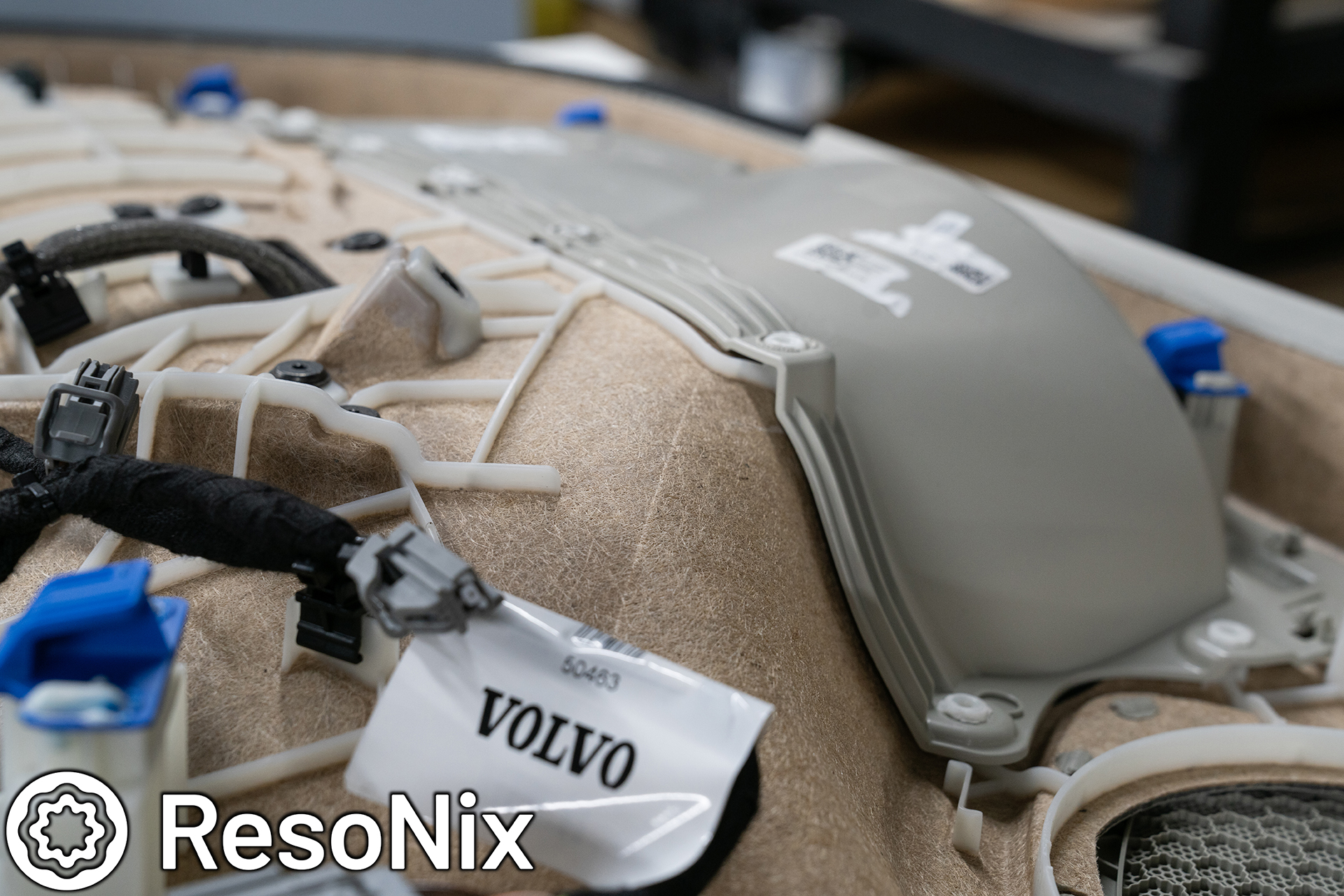
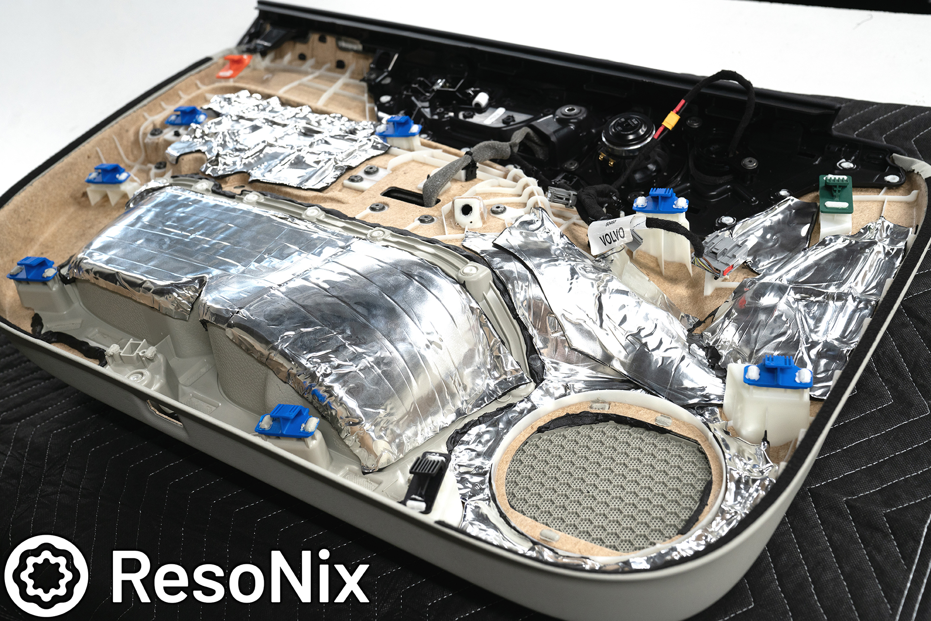
Up next, the door panel sound deadening. This turned into a combination of ResoNix Mega CLD Squares, ResoNix Rope, ResoNix Fiber Mat 25, ResoNix CCF Decoupler 3S, and ResoNix OEM Interior Tape. Unfortunately, I forgot to get photos of the ResoNix Fiber Mat installed. I am not sure how, but I do have plenty of video coming where you can see what I did.
First up, as usual, ResoNix Rope. ResoNix’s Butyl Rope is used on the door panel in between all of the overlapping layers that make up the door panel, and can otherwise resonate and vibrate against each other if not treated. The ResoNix Butyl Rope serves two purposes here. First, to decouple the layers and provide cushion for them to prevent them from vibrating against each outer. Second, to actually hold them in place. The ResoNix Butyl Rope is naturally an adhesive and has the ideal viscoelastic properties to work in this capacity.
Pictured here and in the next couple of photos you can see a couple of specific areas on this door panel that have overlapping layers that are going to be prone to rattling against each other. What I am looking out for here is two overlapping layers that don’t have a large enough gap, or arent completely solid. If I can tap on them with my fist and they “clap” against each other, they need treatment.
The first area that received treatment with ResoNix Butyl Rope is the perimeter of the insert for the map pocket. As seen in the previous pictures, it is an overlapped panel that is only plastic welded in spots to hold it in place. Parts like this are usually hot-spots for rattles and is perfect for ResoNix Butyl Rope application.
Tip: When using butyl rope, take some of the wax paper that comes with/on the ResoNix CLD Squares and use that to press down and put pressure on the Butyl Rope. It’ll allow you to form it without it getting stuck to your fingers which would otherwise occasionally pull it out of place, and also leaves a cleaner looking end result. You can see on the bottom right and right side of this photo have the rope pushed down cleanly and evenly, while the rest is lumpy and clearly done with just fingers so far. Not that it makes a difference in performance, it just makes quicker/easier work of it, and ends up looking a bit cleaner.
The speaker grille area is also a hot spot for needing ResoNix Rope. The overlapping panels being this close to the source of the energy (the speaker) are definitely going to rattle (Having this car, I already knew this spot was a problem in this car, but also working on many cars in my time has let me know that this area is a problem more times than not).
Another area was the bottom of the arm rest. You can see that when I shine a light from down below, you can see light showing the small gap in between the two panels. Again, these will definitely rattle and buzz. Perfect spot for some butyl rope. In a spot like this, I made sure now to push it through, as pushing it through would be visible from the outside of the panel. I just laid it on top and made sure both sides had proper adhesion.
Next up, applying ResoNix Mega CLD Squares to the door panel. Considering the thickness of the aluminum on this new product, it was definitely a bit of a challenge in comparison to our original ResoNix CLD Squares, but by no means was it impossible. Remember, use as large of pieces as possible.
Tip: Use the supplied extra wax paper to make templates.
Next up, ResoNix Fiber Mat 25 Installation. Sorry, unfortunately I apparently forgot to take finished photos of this. I could have sworn I did though. Maybe I accidentally forgot to upload them before formatting the SD card in the camera. Next are some screen shots from the video that I took where you can see the end result of the Fiber Mat 25 Installation.
Tip: also use wax paper to make templates.
Pictured below is a screenshot from the video that shows the completed ResoNix Fiber Mat 25 installation on the door panel. I know, not the best view, but it’s better than nothing. Once the Fiber Mat 25 was installed, the door panels sound treatment was completed.
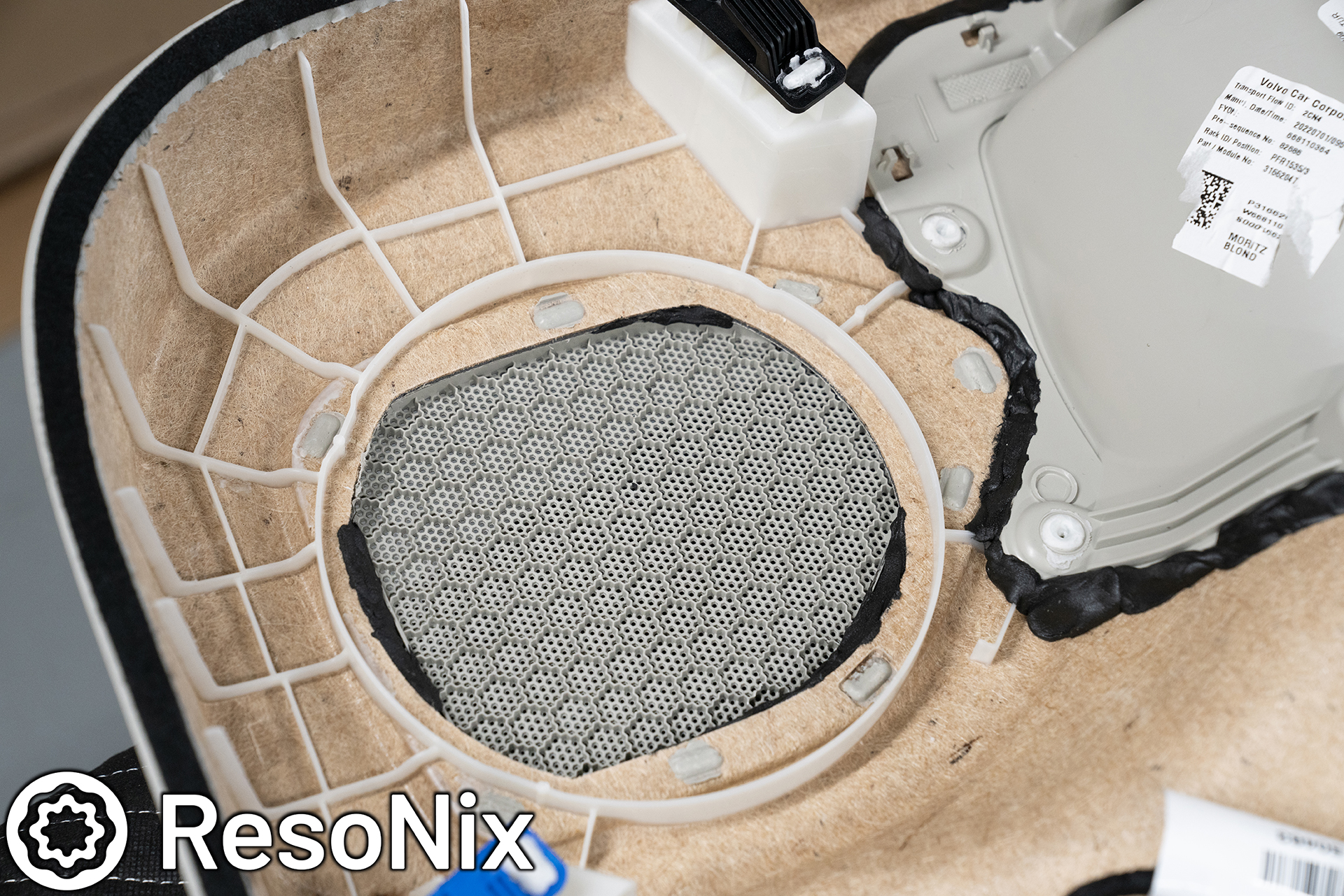
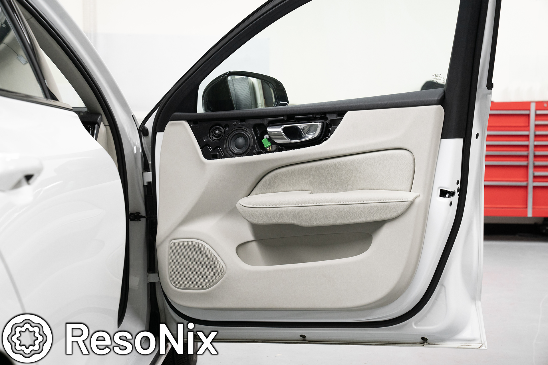
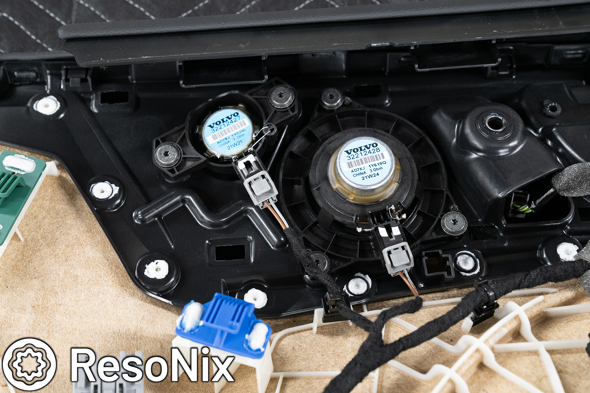
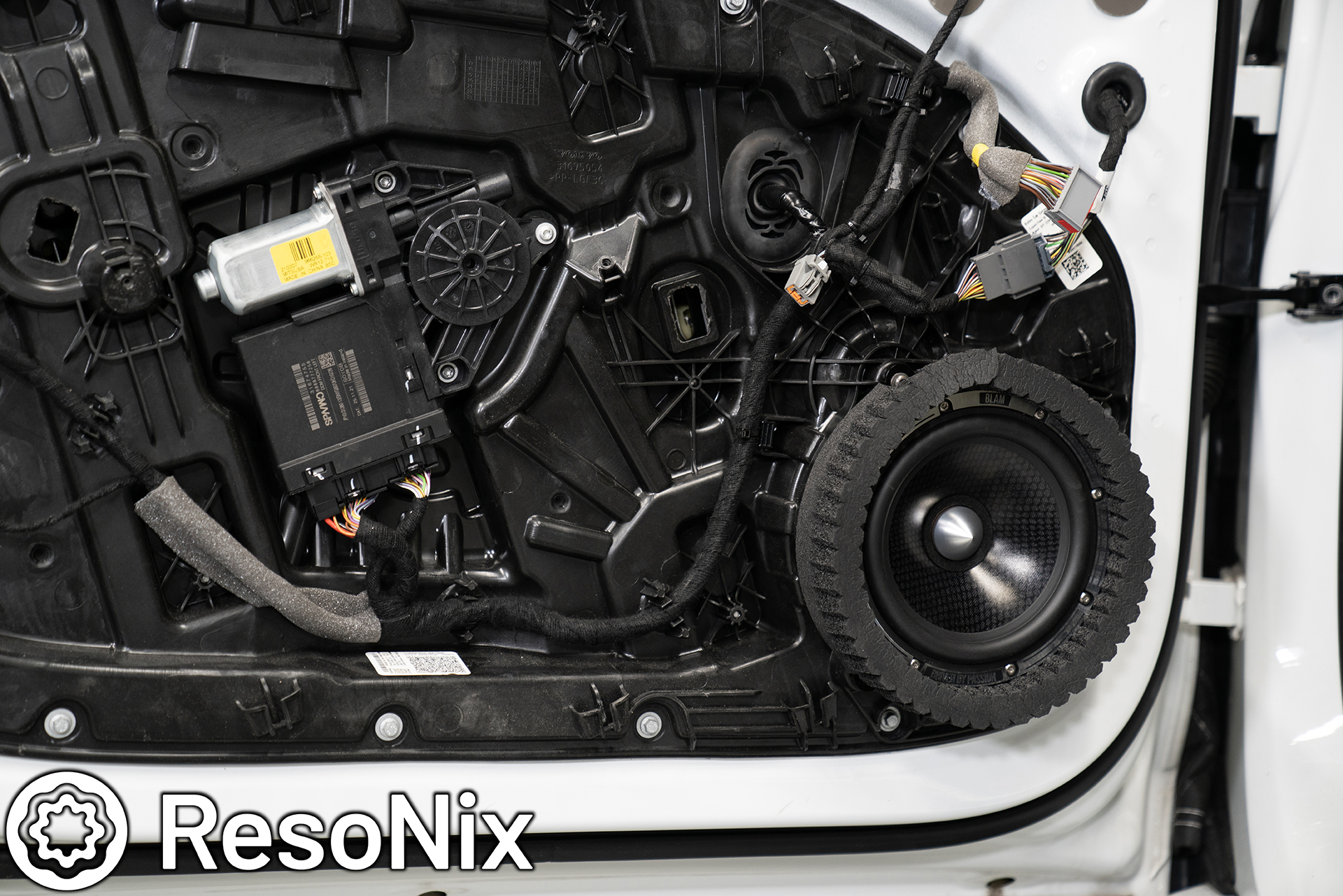
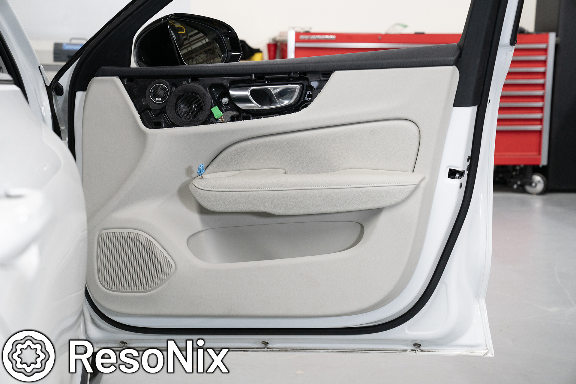
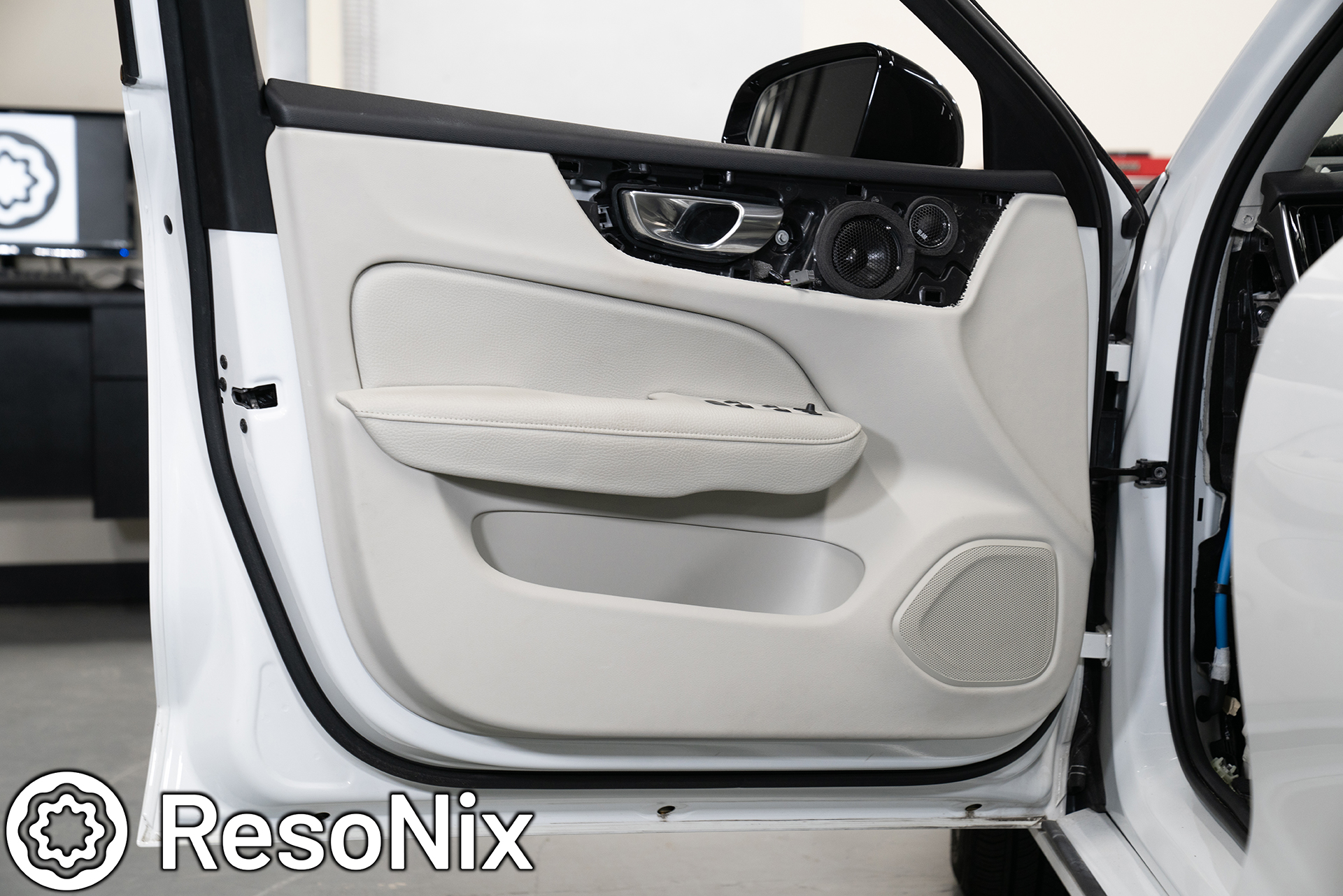
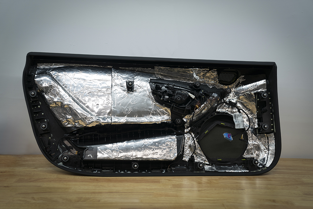
Up next, the installation of the midrange and tweeter into the OEM upper door locations. While I am putting this after the sound treatment portion, this was technically done first. Anyways, on to what I did here. So with everything that I do, I do my best to retain the integrity of the vehicle as much as possible. Every baffle and bracket for each and every speaker is done in a way that matches the OEM speaker mounting pattern and uses the OEM hardware to secure it in place.
That said, the way I look at things, I also don’t want anyone messing with my installation if they aren’t qualified to do so. So what I have started doing is using the OEM mounting for the brackets and baffles, but using 316 stainless steel tamper-resistant machine screws for the speakers, amplifiers, fuse holders, and anything else for that matter. I’m only giving those who aren’t qualified “OEM-level” access, and will not let them ruin what I did, as I have had some unfortunate mishaps with dealerships and independent mechanic/body shops doing things incorrectly after making my previous installs too easy to service. They’re either going to have to call me to ask, and I can properly instruct them on what to do, or its going to be someone who is qualified to work on it.
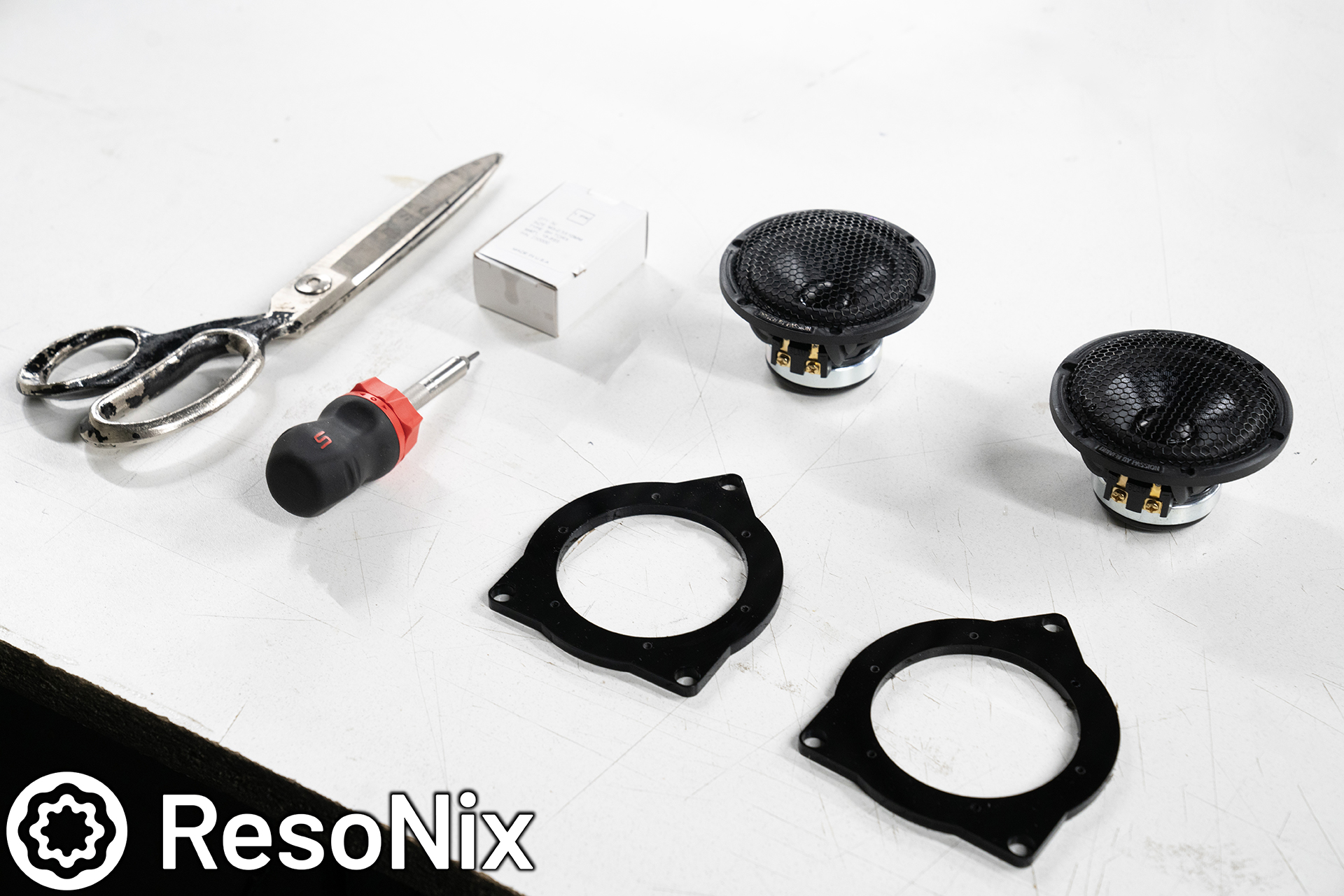
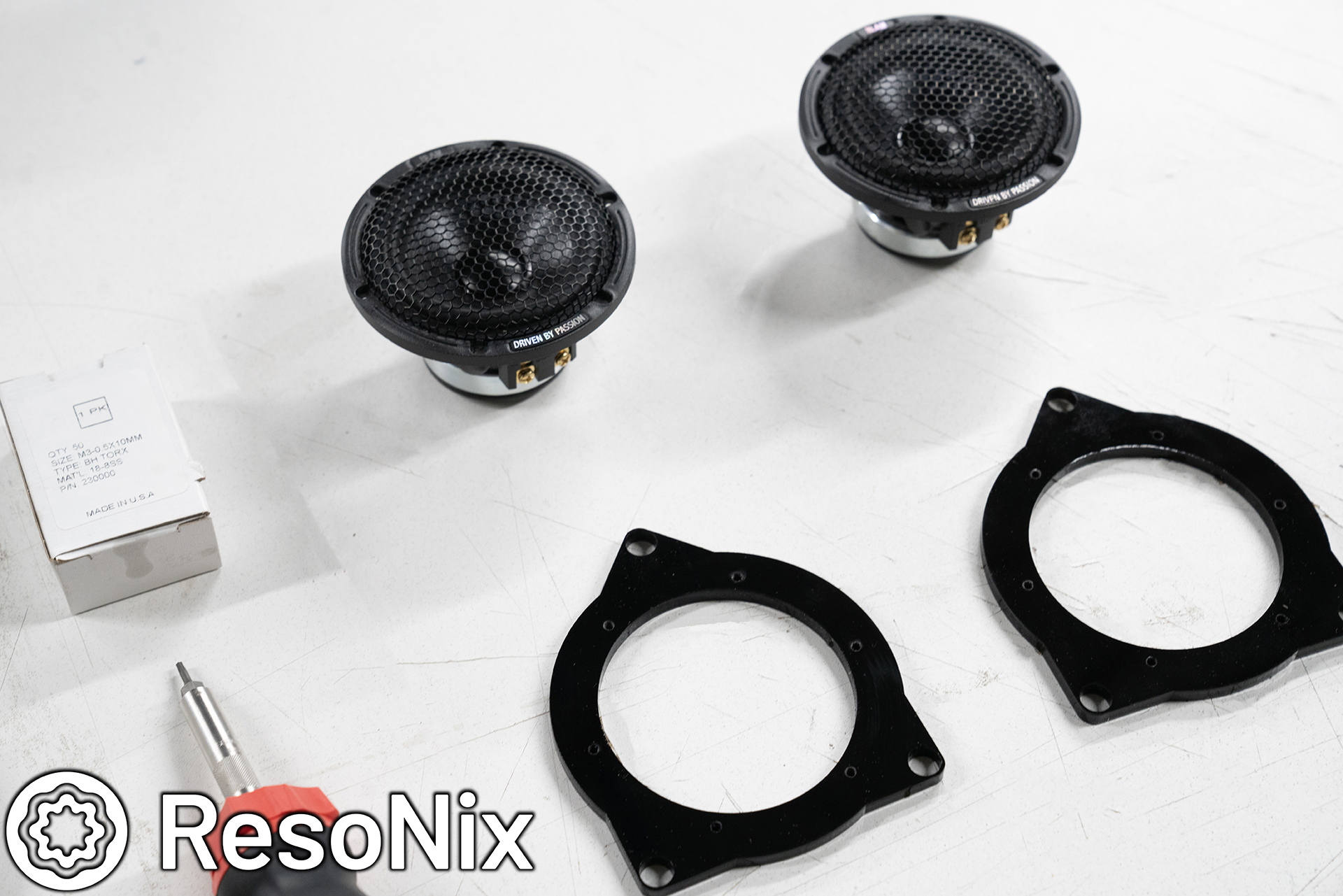
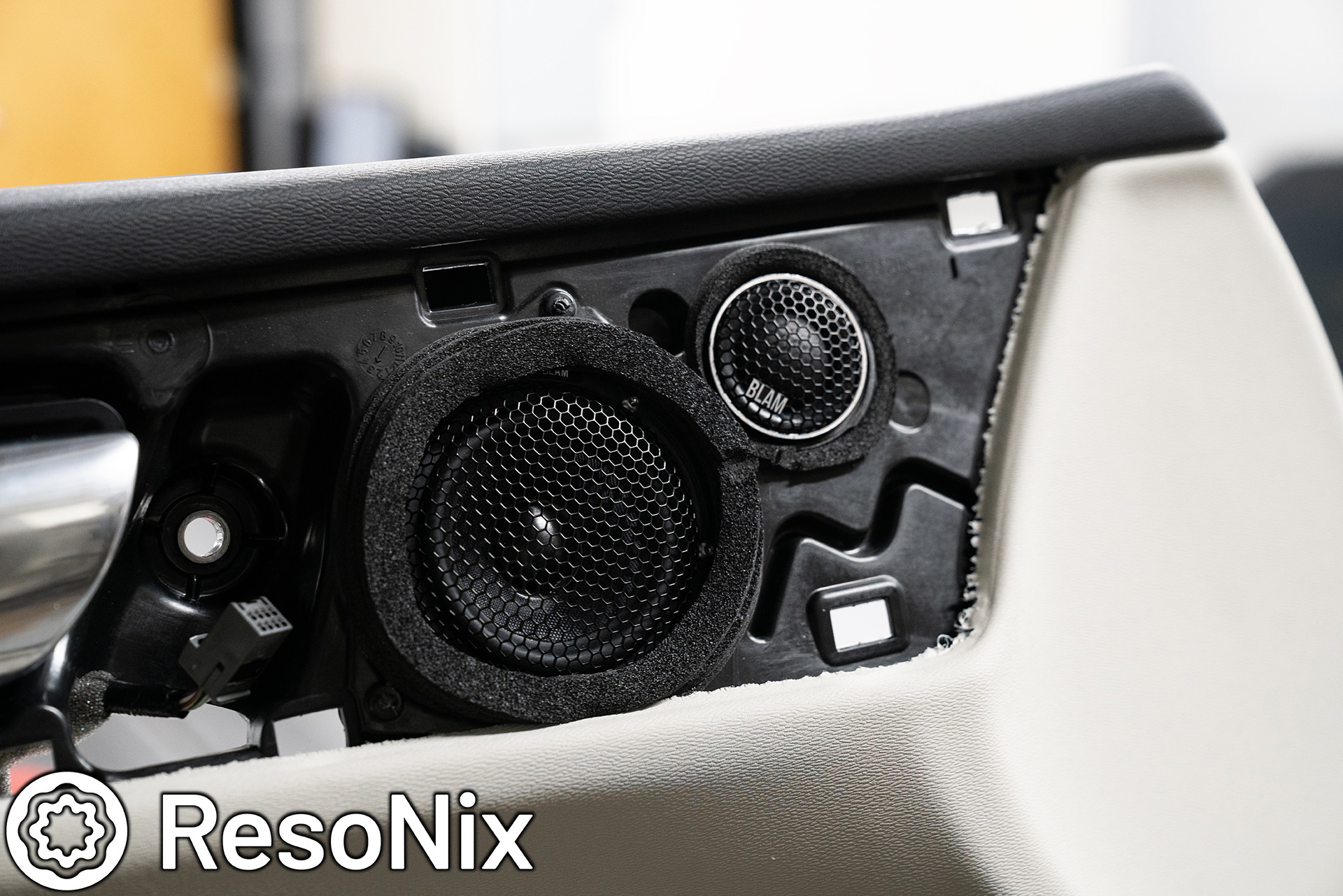
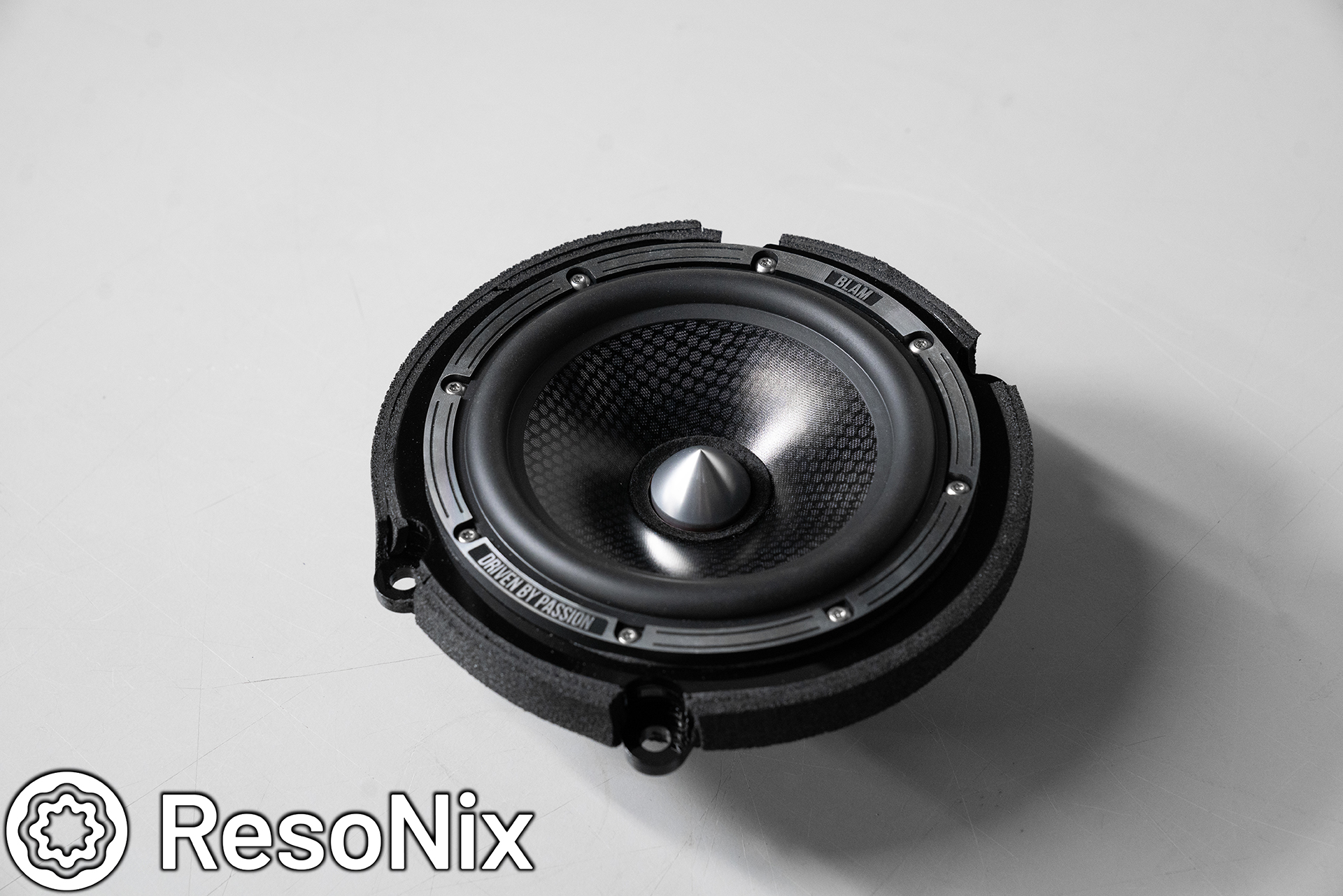
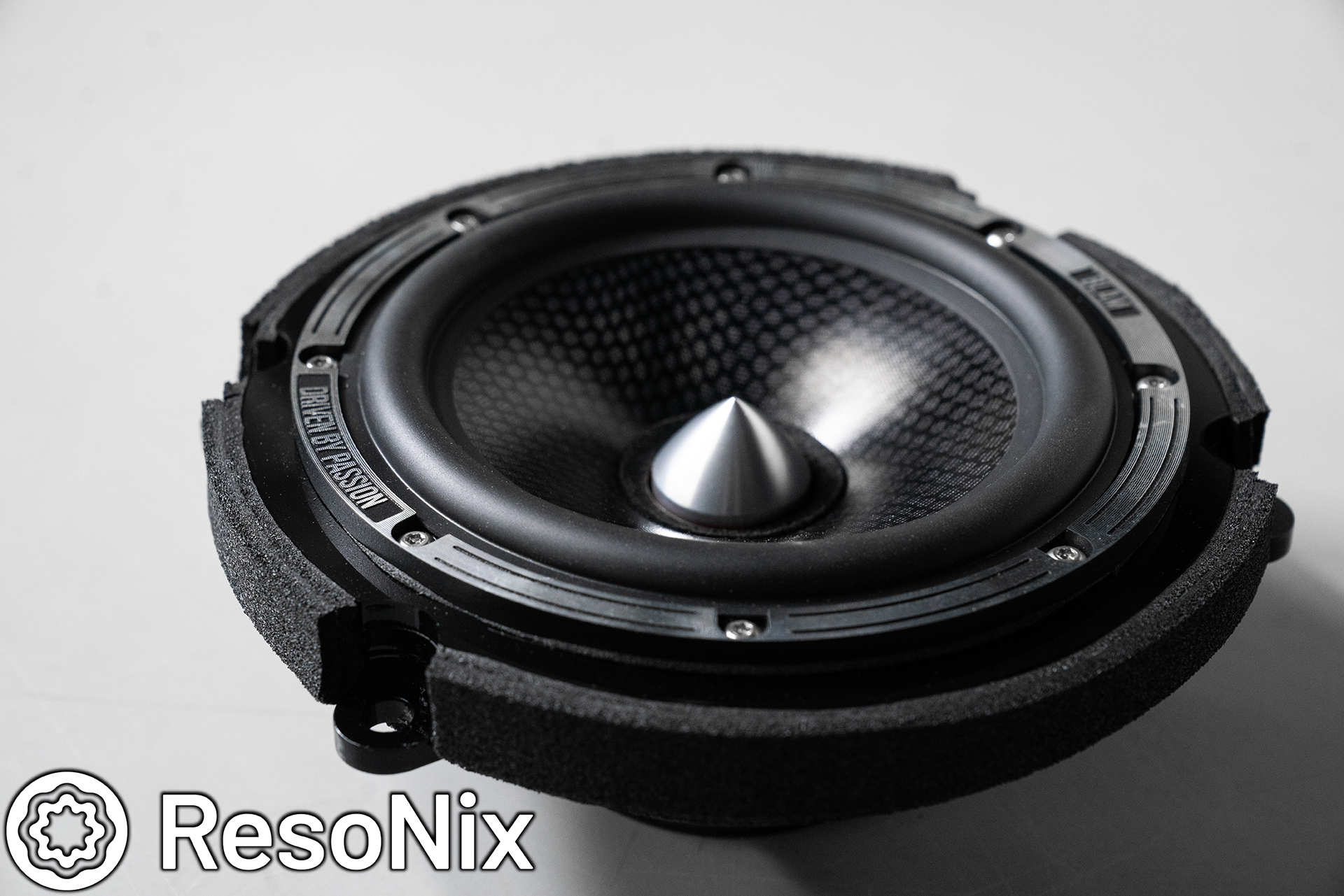
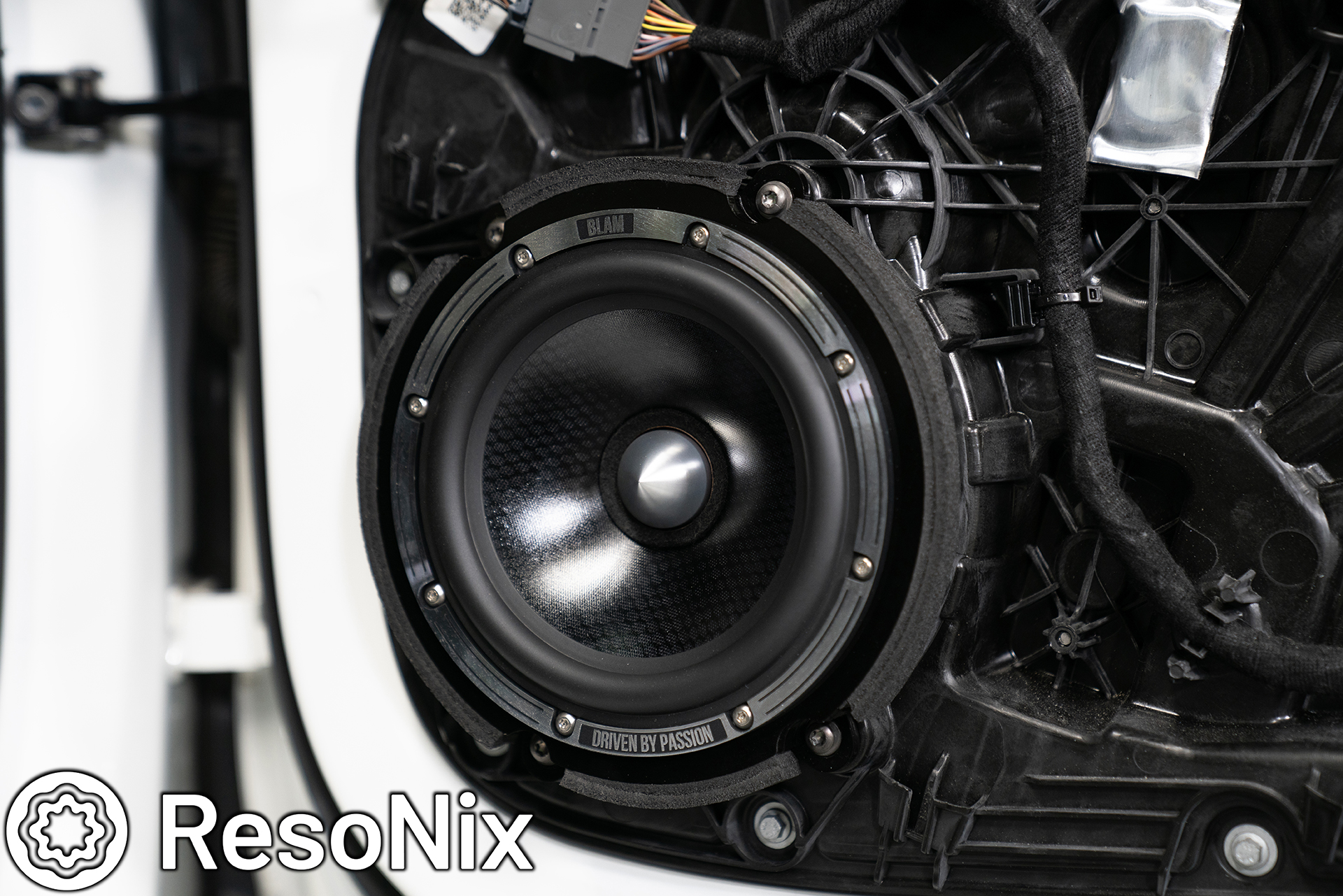
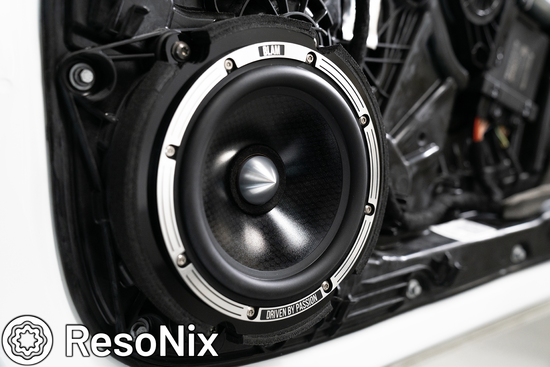
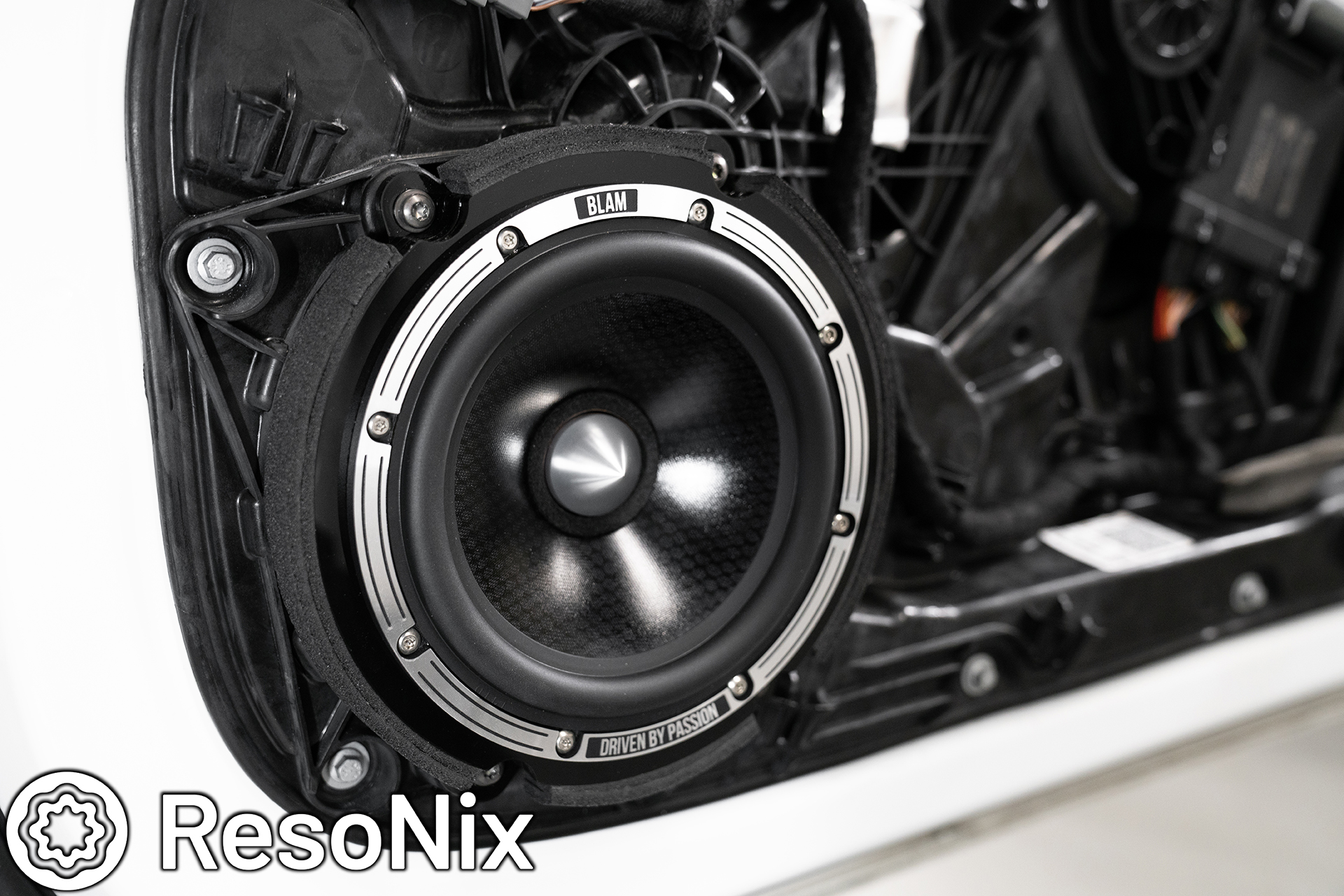
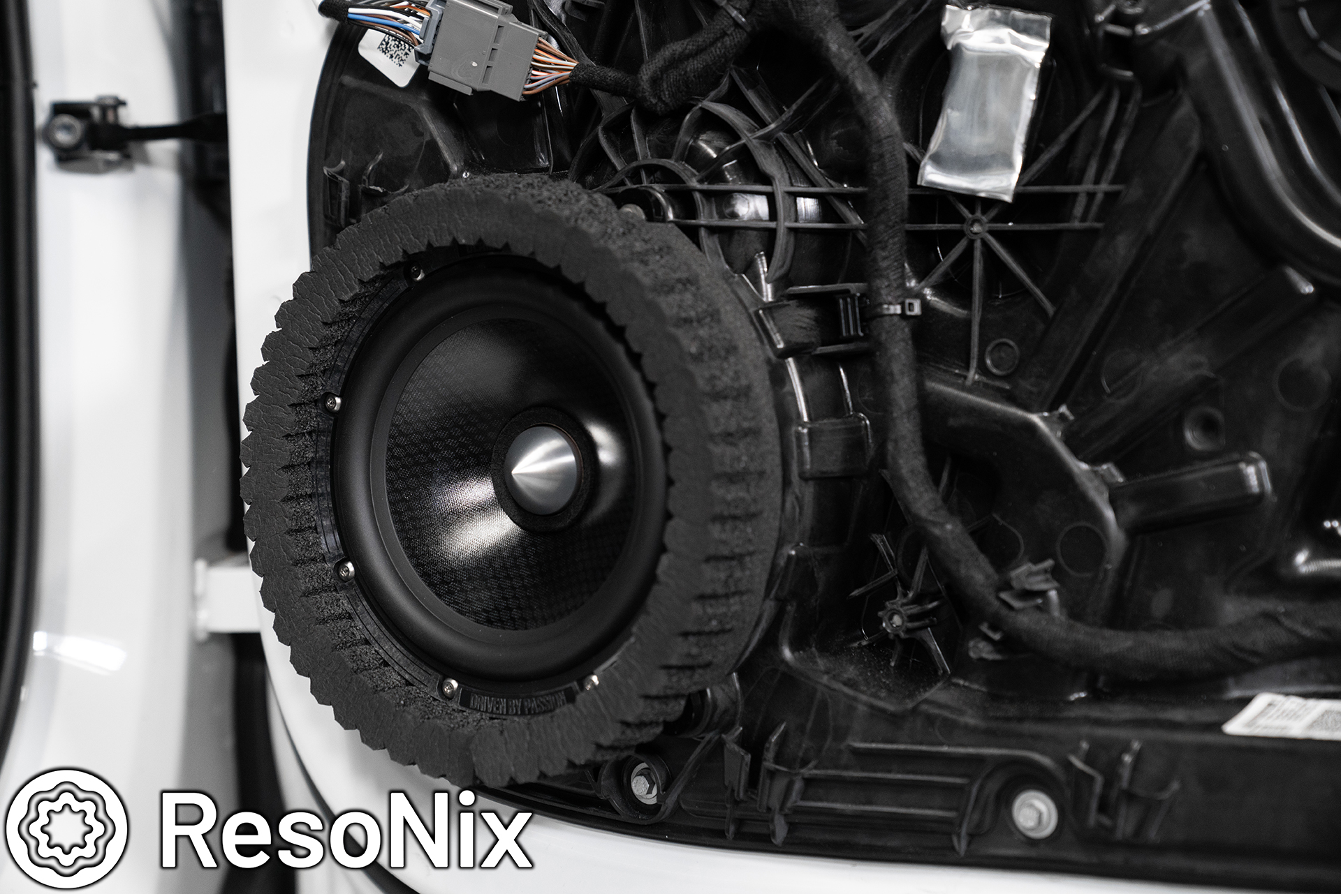
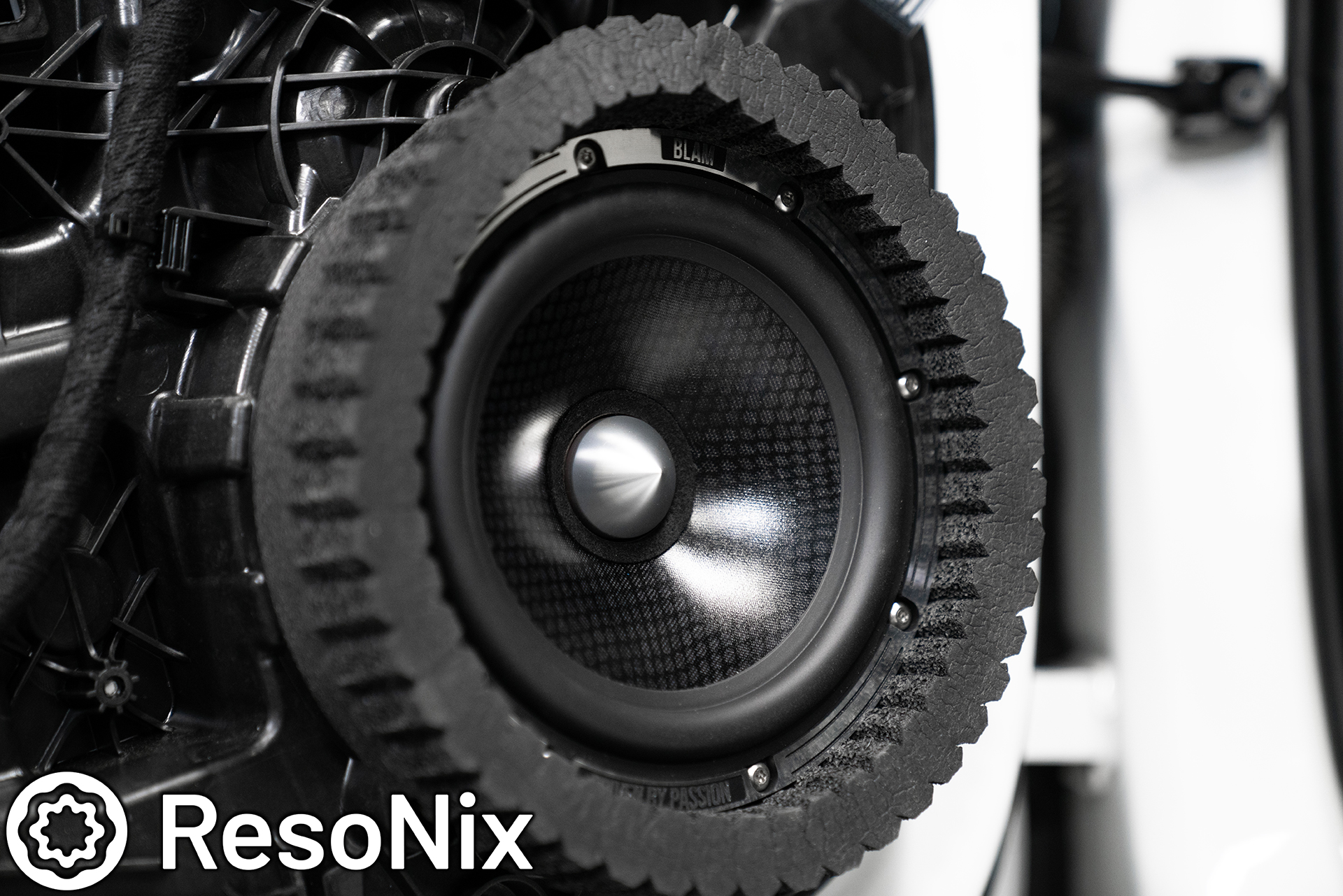
First up, the midrange drivers. We ended up going with the BLAM LFR80, which is a pretty beefy 3″ wideband driver that fits the OEM location in this vehicle perfectly. The baffles were laser cut out of 1/4″ black cast acrylic, and were tapped to accept the M3 machine screws that we used. I unfortunately do not have photos of this next part, but before the midrange drivers were secured to the baffle, I used very thin strips of ResoNix CCF Decoupler 3F as a gasket that was installed onto the bottom of the flange of the driver. This is an important step and is to create an air-tight seal between the driver and the baffle. Without it, very tiny air leaks will occur, and will cause distortion, and will typically sound as if the driver is blown.
Note: when doing this, do NOT include gaps in the gasketing material for the screw holes. This just allows the gasket to act as a “riser” and the screw hole areas now have a gap. Instead, wrap your gasketing material (preferably ResoNIx CCF Decoupler 3F) all the way around in one piece, and pierce holes through the material through the drivers mounting holes.
The drivers were secured with the aforementioned 316 stainless machine screws with a perfect length to make it all the way through the baffle, but without protruding.
Once the midrange was secured to the baffle, another gasket of ResoNix CCF Decoupler 3F was placed on the door panels midrange speaker opening. The purpose of this again is to make sure everything is sealed and there are no leaks or destructive interference. Again, air leaks will rear their ugly head as audible distortion. Taking the time to make sure that these wont happen before they even show is crucial. Little things like this are what people mean when they say “install is the most important aspect of making a car audio system sound great”… All of these little steps make up the “install”.
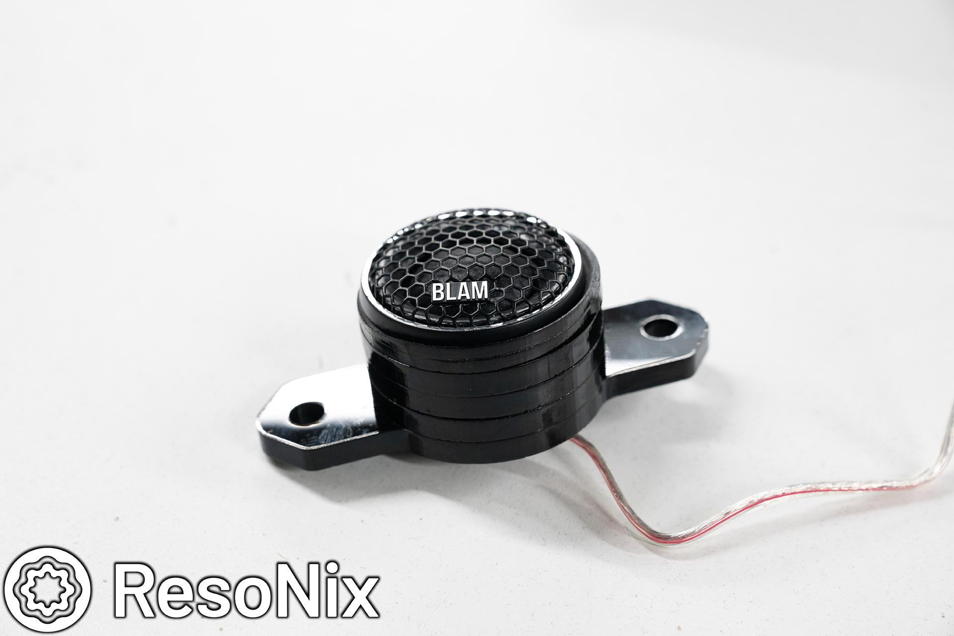
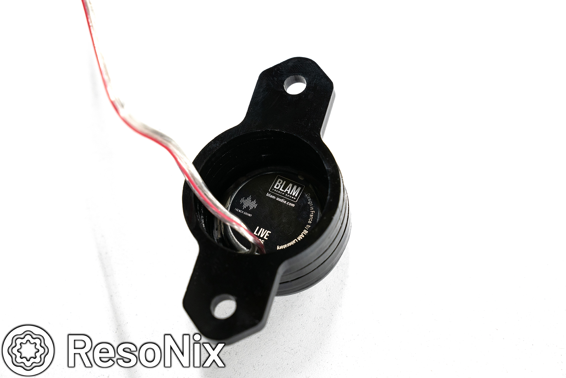
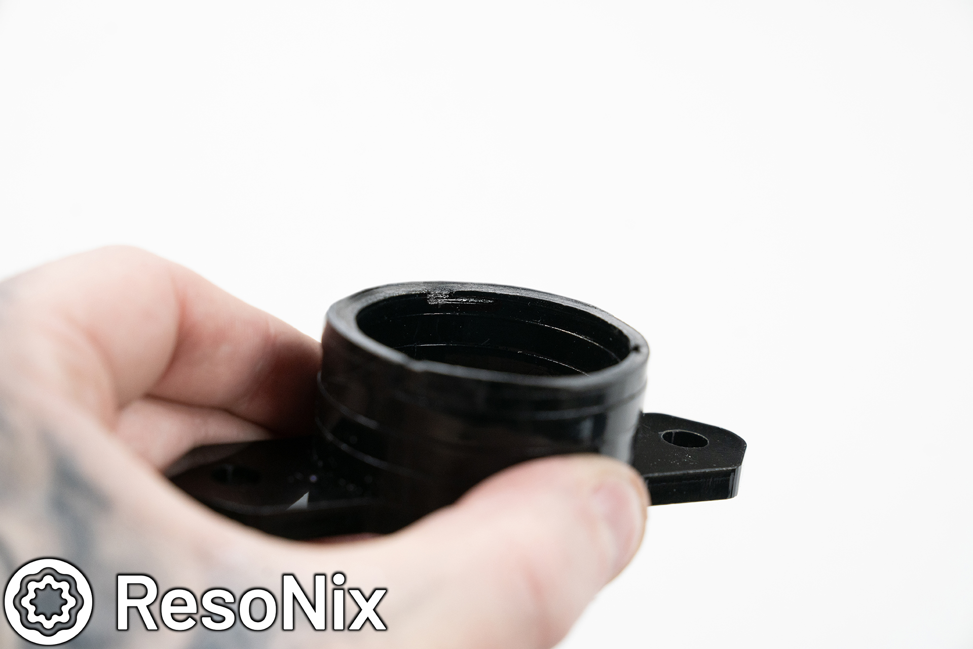
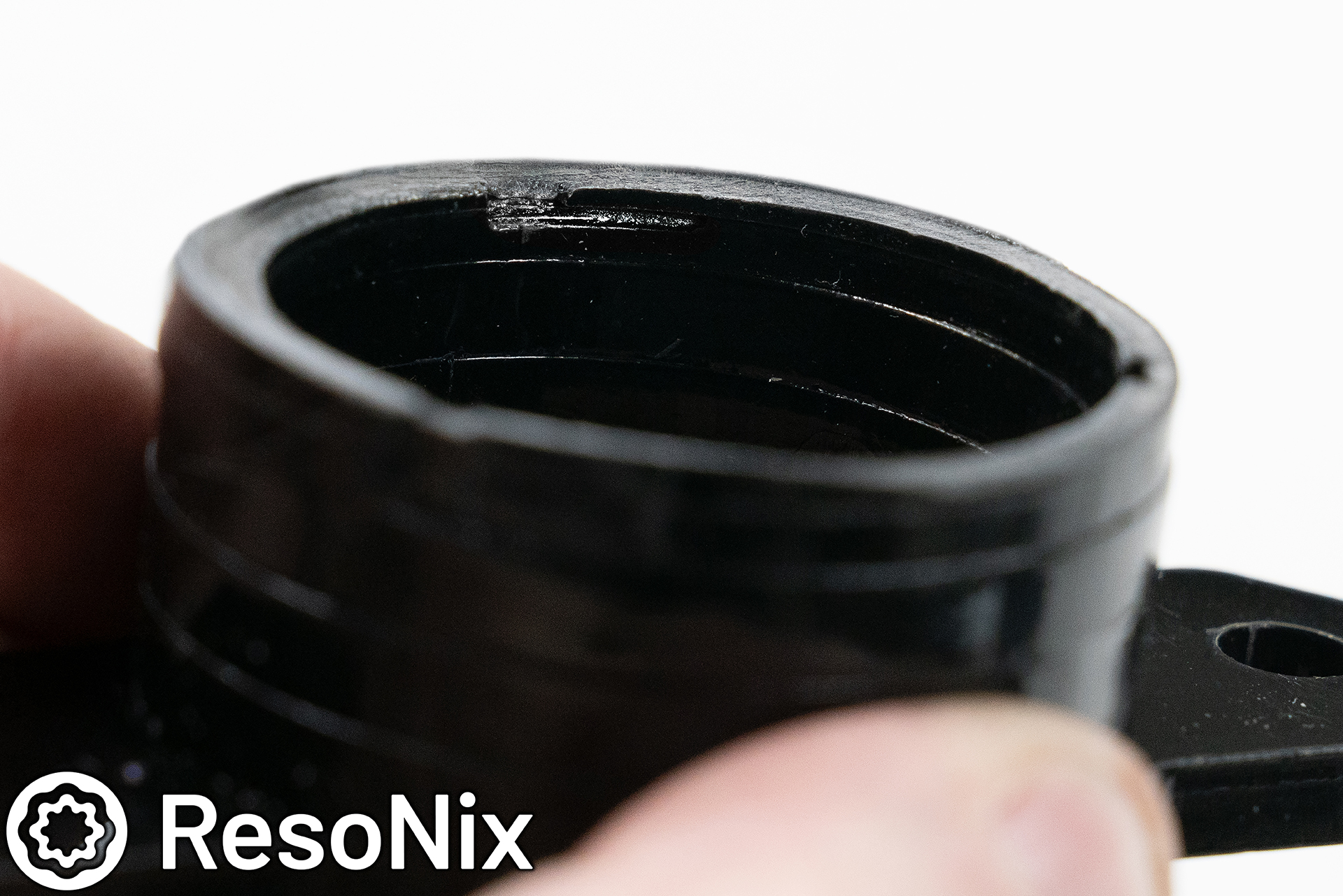
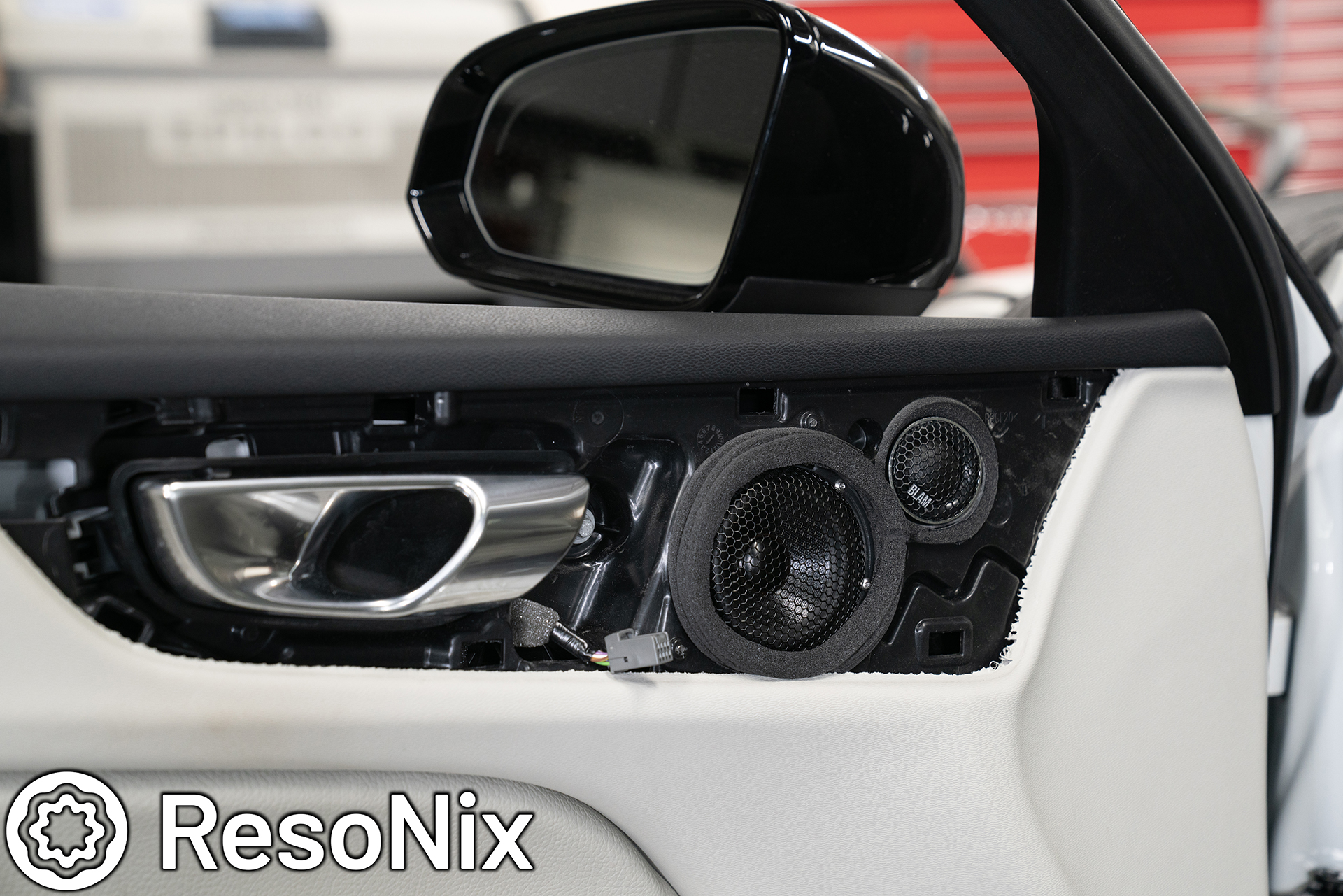
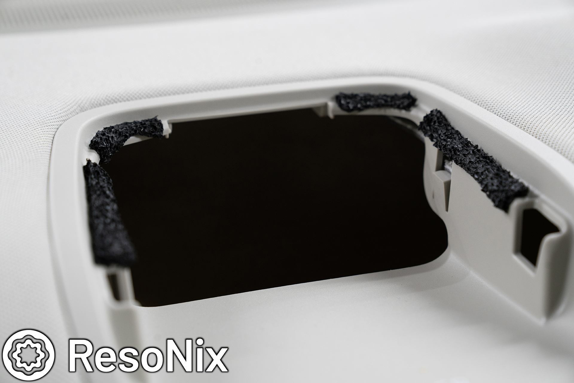
Next up, the tweeter mounting cup and bracket. The BLAM Live tweeter was fully removed from its housing, which left us with some “twist lock” tabs on the tweeter. What I came up with was a cup that secures the tweeter utilizing its own twist lock tabs, and is connected to an OEM-matching bracket that secures using the OEM mounting holes and hardware. The result is a tweeter bracket that places the tweeter only a few mm away from the grille (not sunken back an inch like I see many installers doing because that is the quickest and easiest way. Shame.. Remember, install > everything).. and allows the tweeter to secure using its own tabs. No glue or adhesive required, leaving the tweeter fully in tact and easily removable and can be used in the clients next vehicle, and retains their value if he decides to sell them and upgrade to something else. Glueing them would render them permanently affixed to the vehicle specific bracket, and make the housings unusable, rendering them nearly worthless to any potential buyers, or make things more difficult when it comes time to install them in a new car.
In some photos below, you can see the slots that were engraved into the acrylic to create the pattern that allows the tabs to lock into place.
On the front, I also used ResoNix CCF Decoupler 3F to create a seal for the tweeter (to prevent the rear wave of the midrange driver from leaking in and causing cancellations), and used it to create a sealed ring around the midrange driver that seals it to the trim panel and grille, which will “funnel” all of its energy into the listening space instead of allowing a large portion of it to travel behind the trim panel, where it will introduce resonance, rattles, distortion, and lost output. In hindsight, I could have used a ResoNix CCF Strip for this, but I didn’t think it would take 3 layers of the CCF3F in order to make full contact with the trim panel/grille all the way around (highly important, otherwise its nearly useless). But the CCF3F is also stiffer, so it does provide some stability as well, which helps prevent the trim panel from rattling.
As you can see, the tweeter fits snug within the opening with the installed strip of ResoNix CCF Decoupler 3F. The CCF3F rings around the midrange were stacked a bit higher than necessary, but the more pressure without causing issues with the trim panel, the better. The clips for this trim panel are very tight, so it held the pressure no problem.
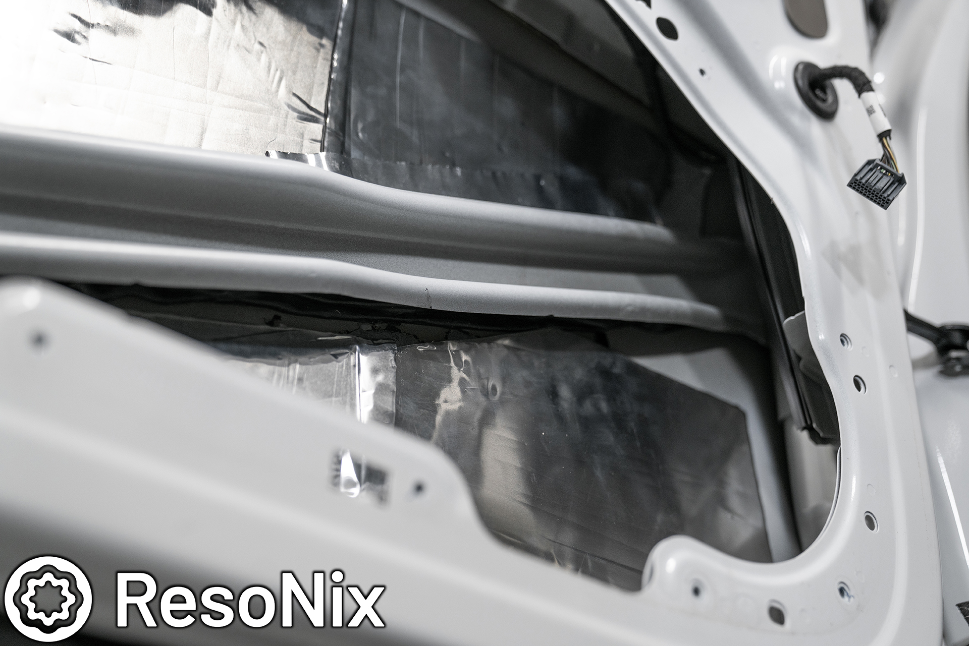
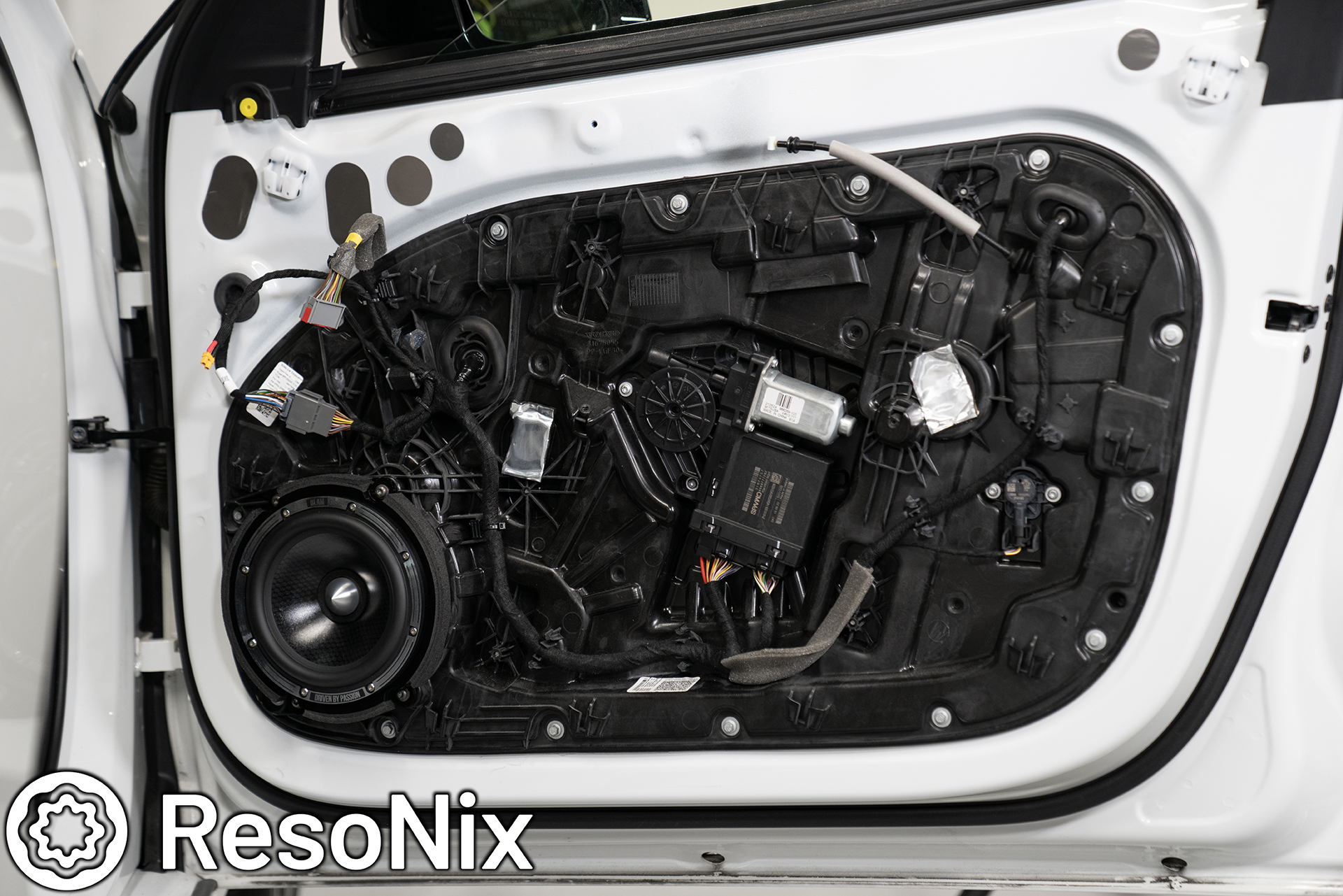
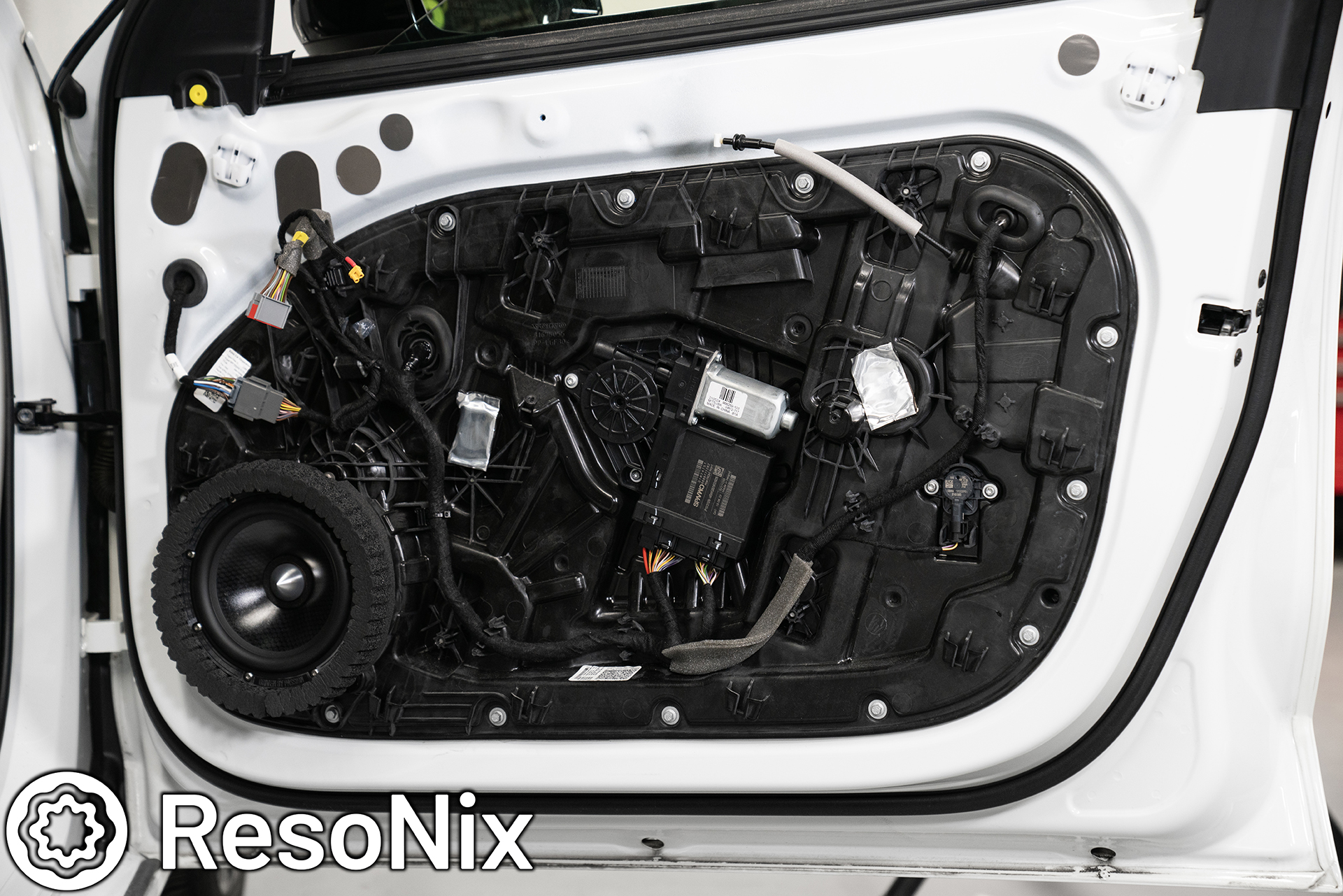
Okay, now onto the midbass driver installation. Once all of the outer door skin’s sound deadening was done, I was able to reinstall the inner door skins access panel and move on to the midbass installation. First thing I would have normally done is remove the OEM speaker and trace the mounting shape into CAD and creating the template to mount the new midbass driver to the OEM mounting points. Fortunately for me, I already have that design from doing my own car in the past. So I moved on to cutting them out on the laser. While the laser was chugging along, I removed the doors. Yes, removed the whole thing. Believe it or not, it is very easy on this car and is the easiest way to run the speaker wire through the molex plug, which is a very tight fit. I ended up running a 4-conductor 16 gauge wire in, two of which are used for the midbass, and the other two just in case. It always pays off to plan ahead and build in redundancies.
Door removed. I made sure to protect the fender with a clean blanket. Ended up not needing it since Volvo makes it pretty easy to do this, but better safe than sorry.
Here you can see the vehicles side of the molex plug. At the bottom, you can see a circle. That circle has a small opening where you can run wire through. I ran the wire in the removed door first, and left PLENTY of slack on the side exiting the door that will be ran into the vehicle. This was a bit difficult as it is, as mentioned, a very tight fit. Patience and the right tools made this work in the end without the need to modify the plug in the slightest, I then brought the door on its stand close to the vehicle so I can run the wire through the other part of the plug that is mounted to the car.
Things get tricky again when running the wire into the car from the door.
1) The two circular openings in the plugs mate up to each other, so there is NO room for slack or bends or twists in the wire. When you run the wire all the way through into the car, you need to pull it tight as you bring the plugs together.
2) The molex plug runs into an enclosed cavity in the kick panel that doesn’t have any real access besides for a tightly packed grommet with wires run through it. You need to make a small slit in the bottom of the grommet and get very lucky fishing the wire into it. It took about 15 minutes per door to do both steps, so not impossible, just frustrating and tedious.
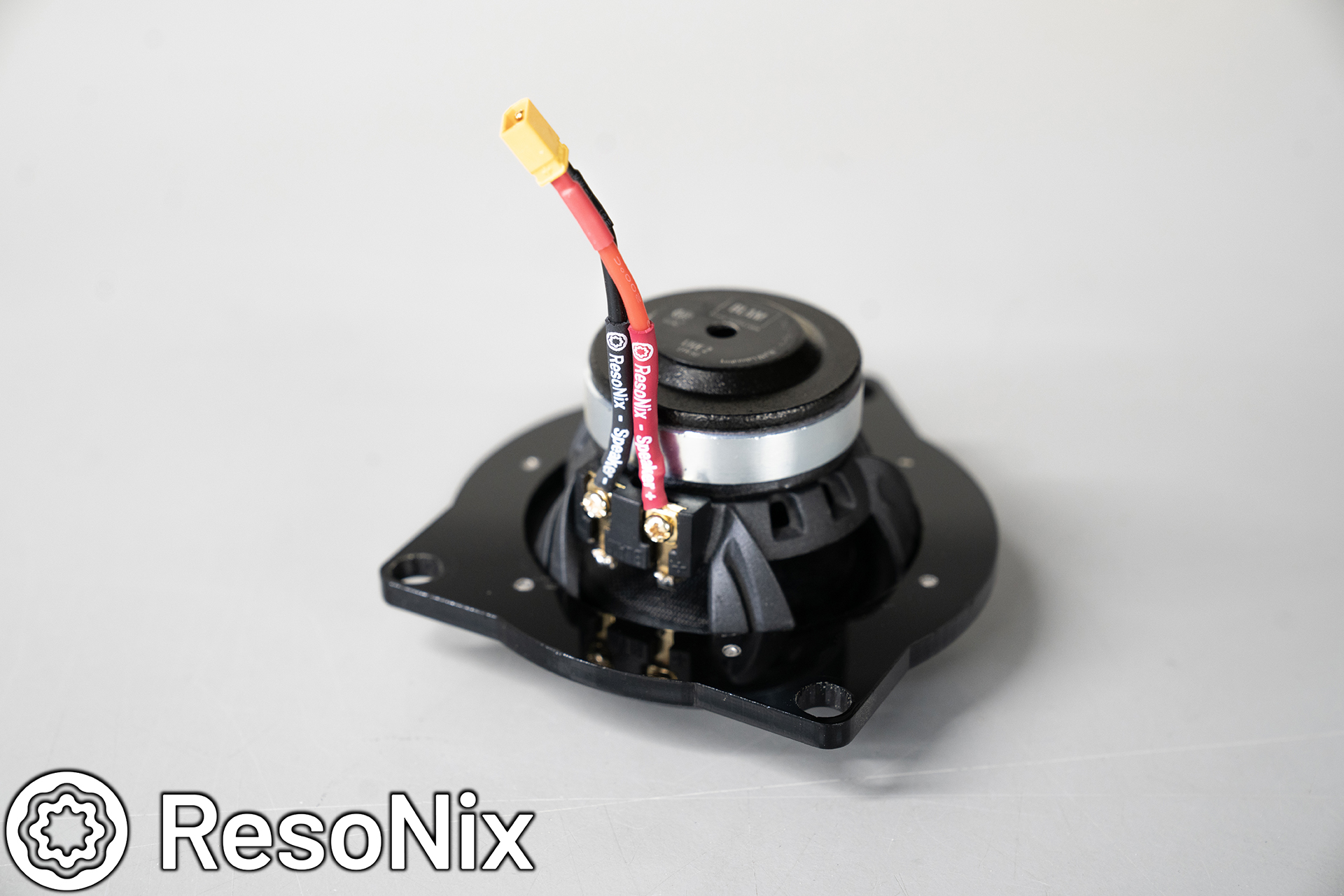
The wire in the door was ran to the midbass opening, where it was zip tied out of the way along the structure of the opening. It was terminated with an XT30 connector, and dressed with the ResoNix OEM exterior tape.
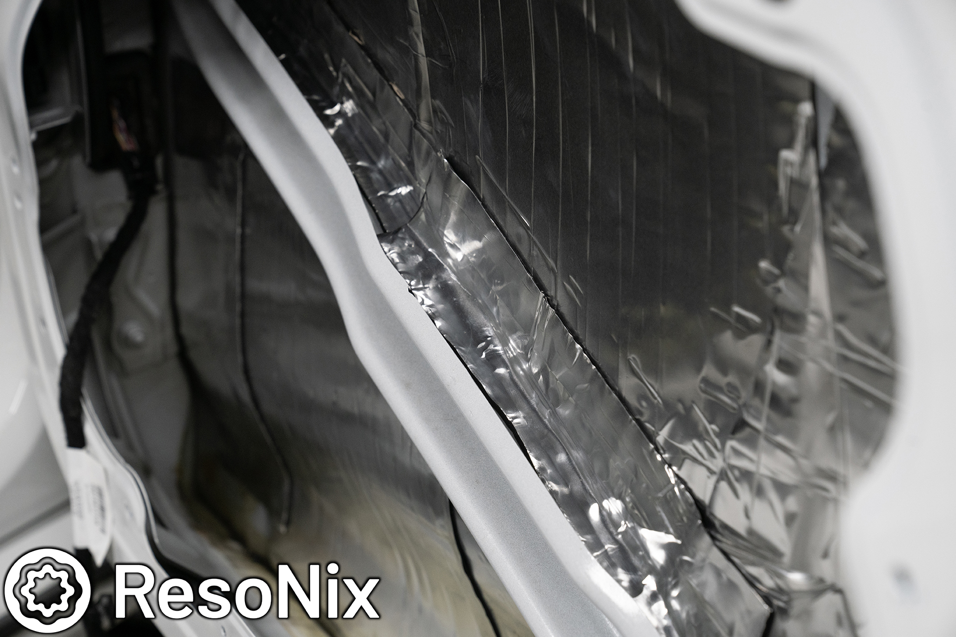
While the door was off, I also ran the wire for the tweeter, which ended up being the OEM midbass wiring, just repurposed for the tweeter. This was all dressed with the ResoNix OEM Interior tape, which is also the same tape that Volvo uses.
Midbass driver installation: Continued.
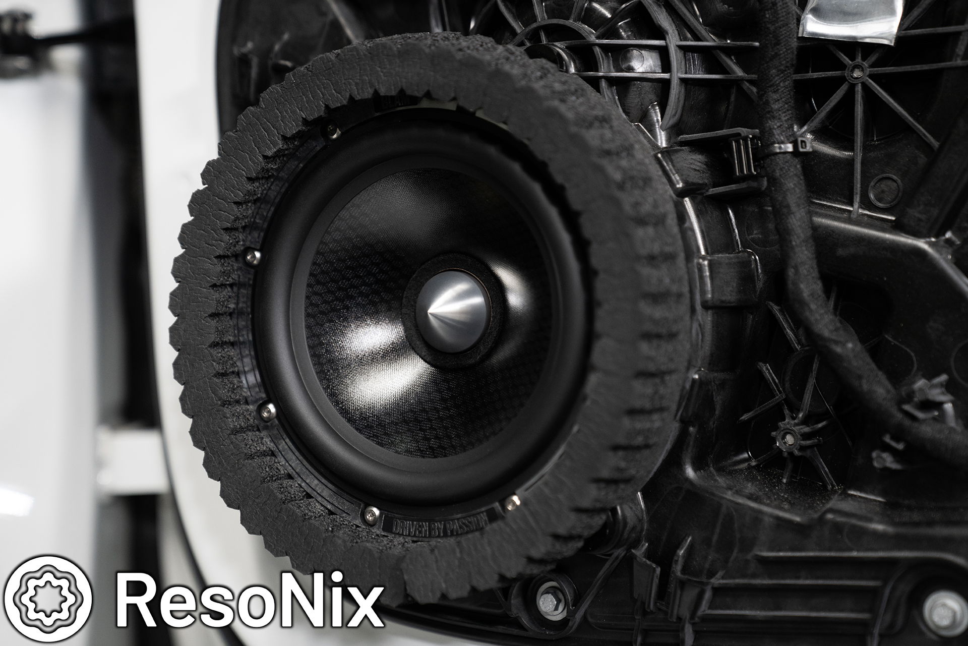
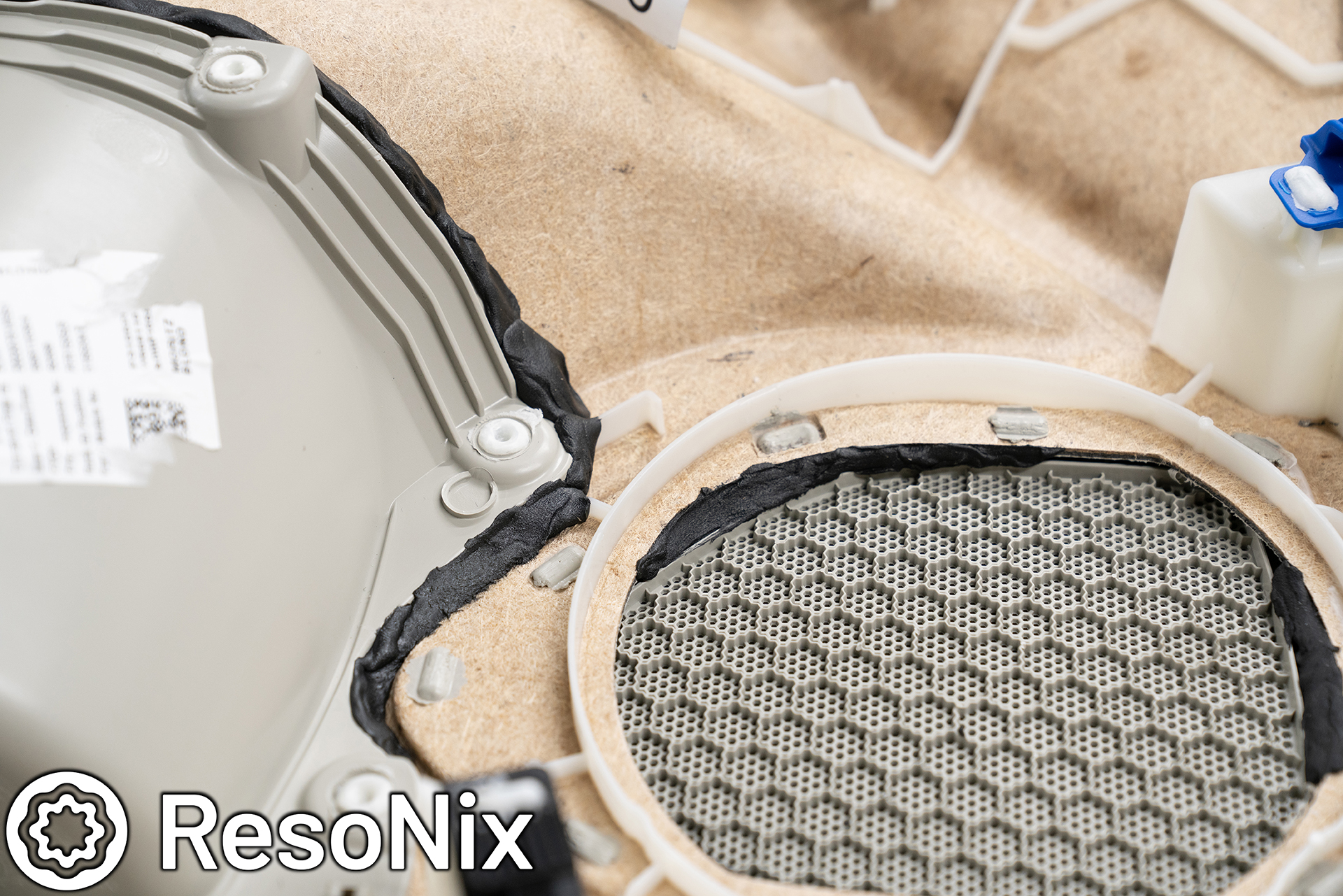
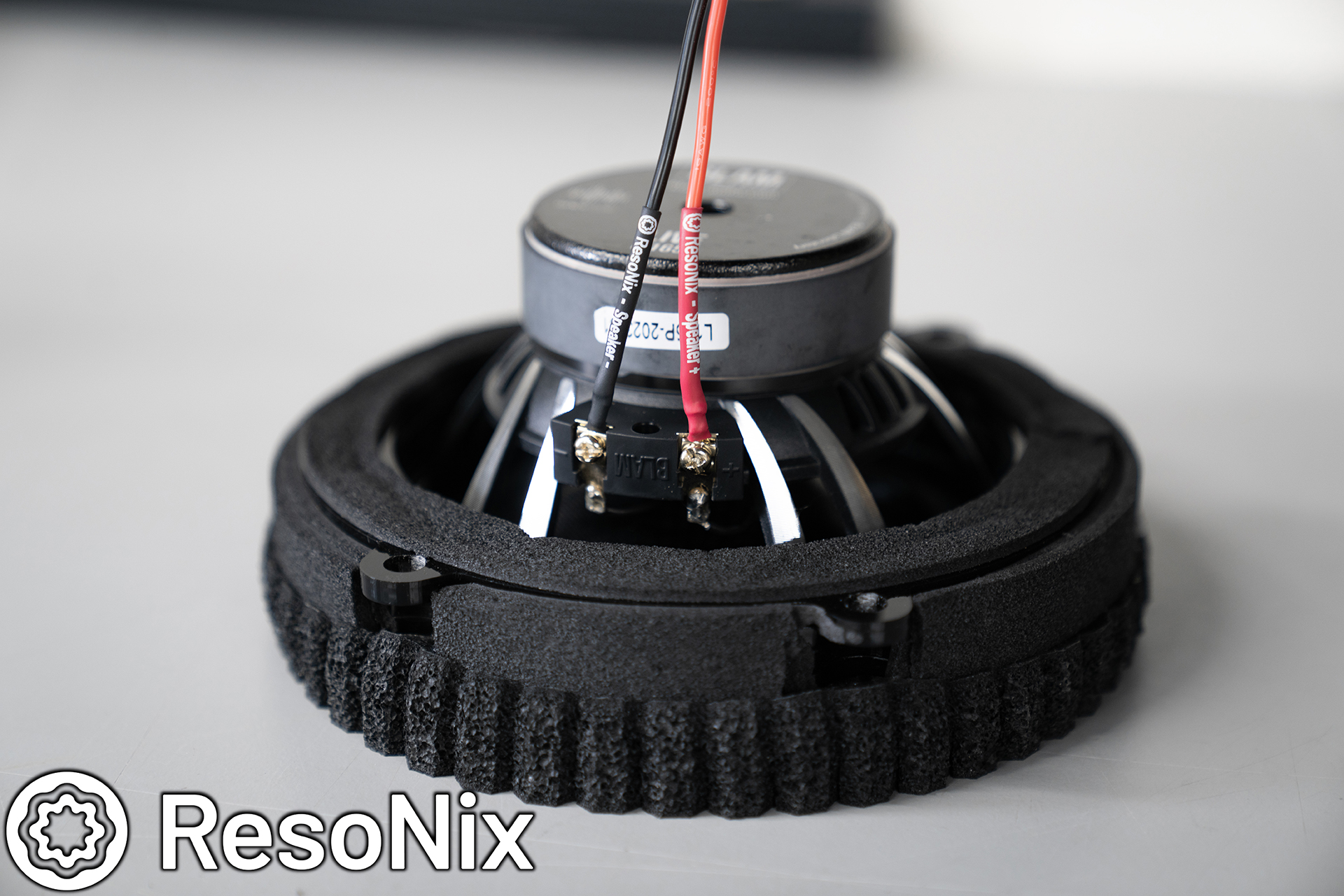
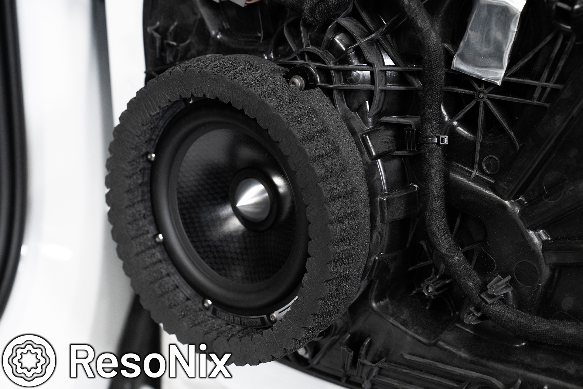
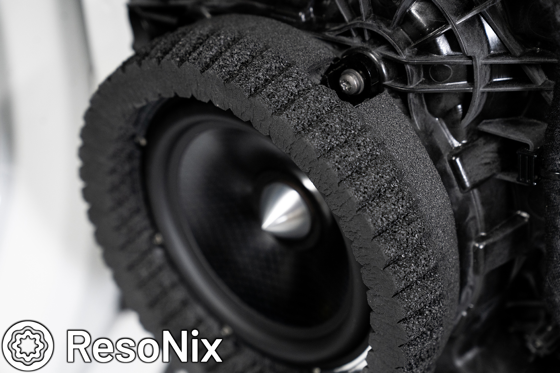
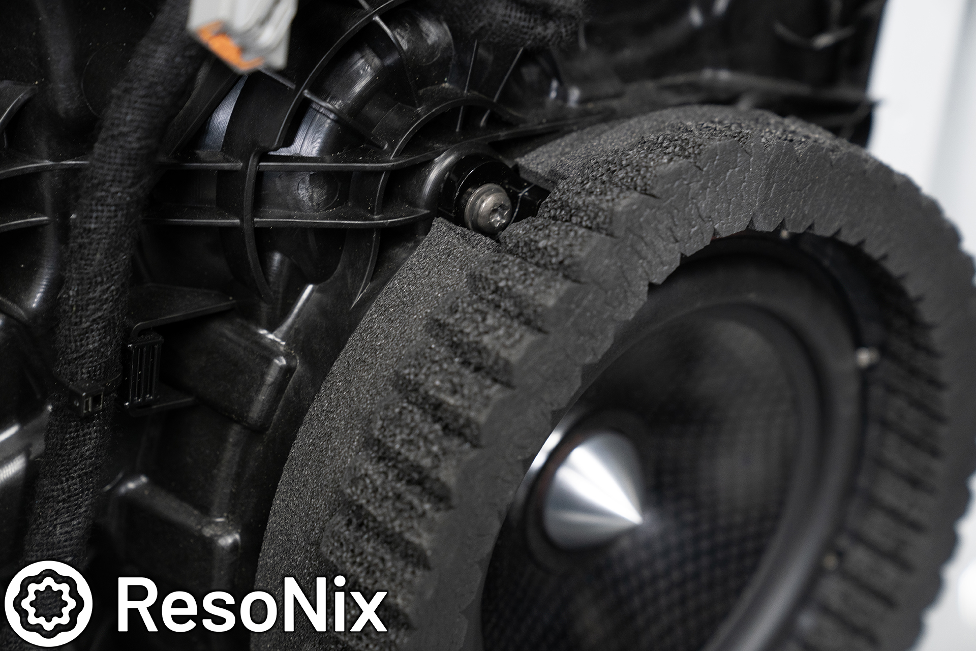
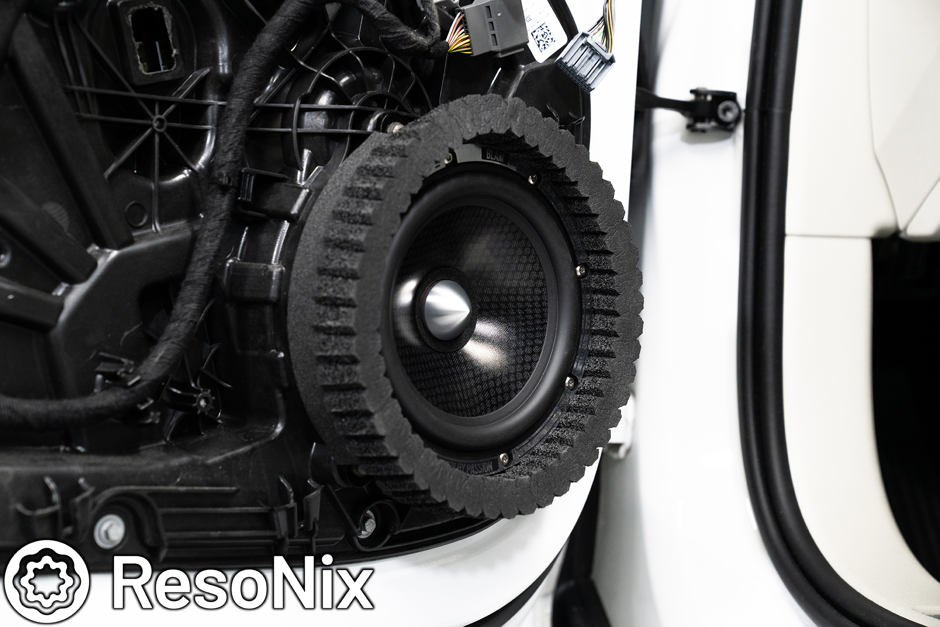
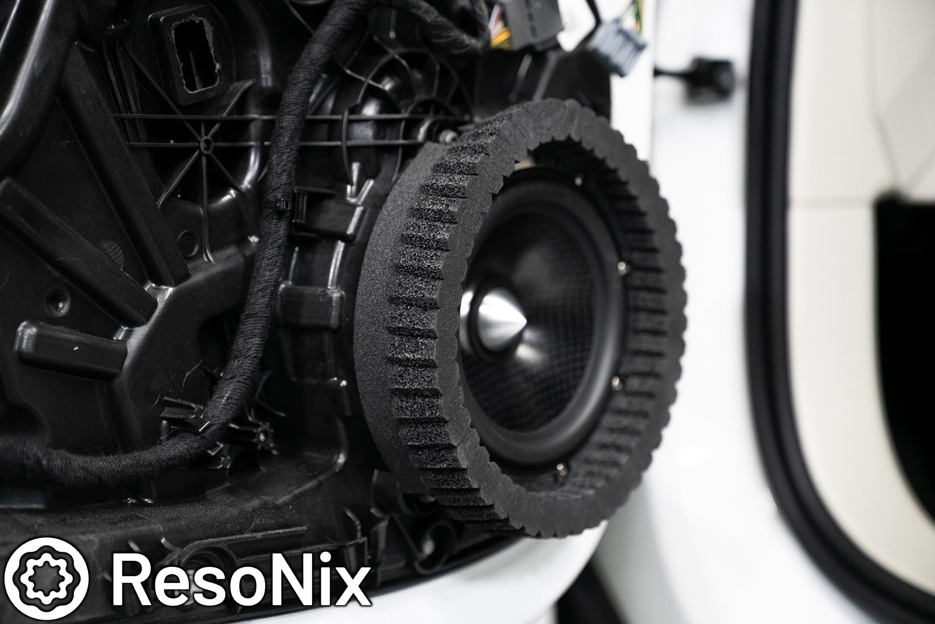
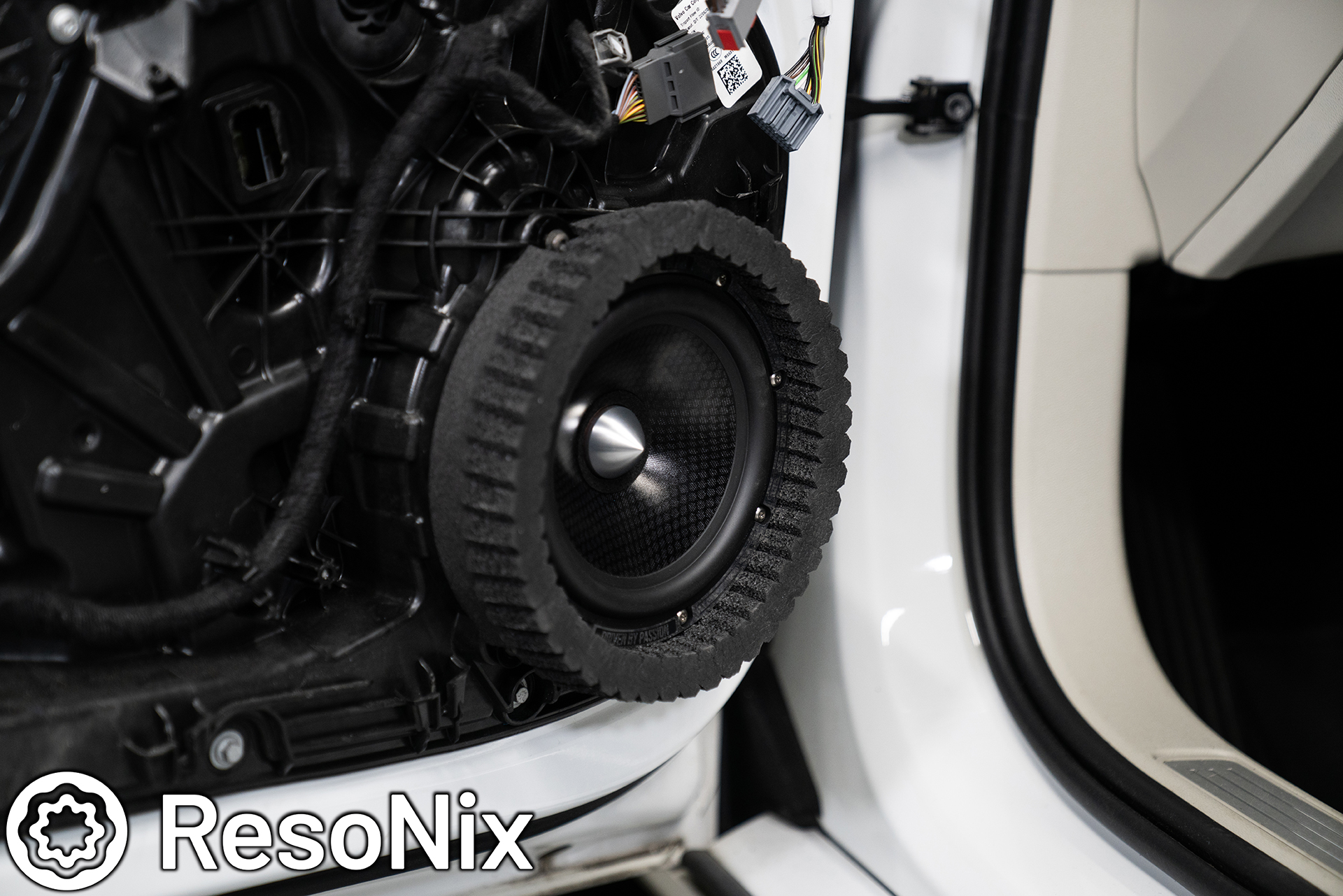
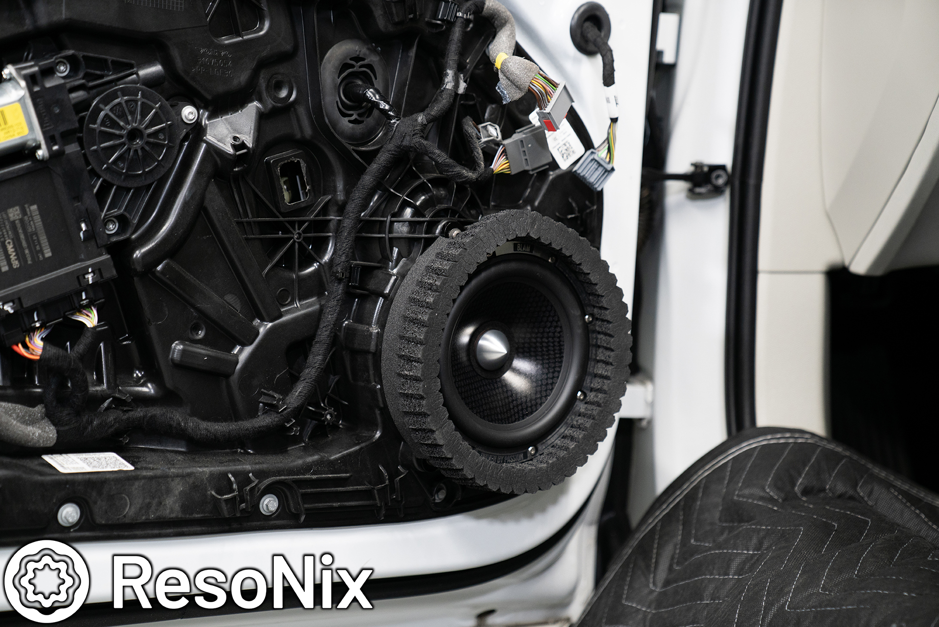
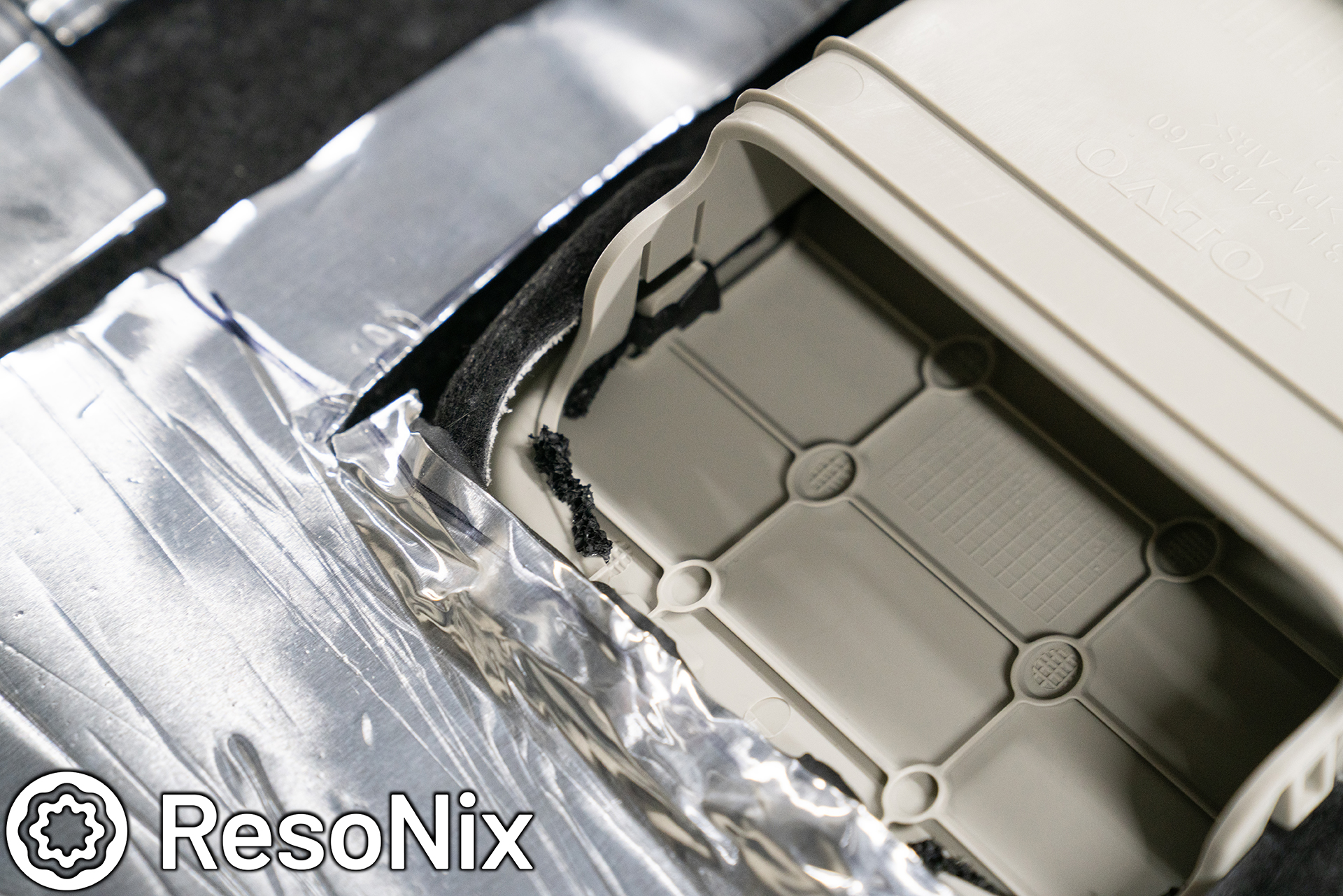
The 4-layer, 1-inch thick total baffle for the midbass driver was constructed out of black cast acrylic on my laser. The base layer has the mounting pattern for the OEM mounting points and makes use of the OEM hardware. The driver was secured to the baffle via M4 x 25mm 316 Stainless Tamper-resistant machine screws. Before the driver was secured to the baffle, I also used a strip of ResoNix CCF Decoupler 3F along the entire perimeter of the bottom of the mounting flange in order to create a perfect seal to prevent air leaks. Not only was this done on the bottom of the driver, but this was also done on the bottom of the baffle so that there are no air leaks between the inner door skin structure and the baffle. After that, I also neatly adding two layers of CCF Decoupler 3F to the outer perimeter of the baffle. This served one main purpose. You can see that I extended the outer diameter of the baffle to be larger than the outer diameter of the midbass driver itself. This was so I can mount the ResoNix CCF Strips around the driver without actually adhering it to the driver itself. Sometimes, that has to be done due to size constraints, but in this case it wasn’t necessary. That said, I wasnt able to extend it to fit the full width of the ResoNix CCF Strip without getting nervous that it would hit the door panel and prevent it from being able to be reinstalled. So, I added the ResoNix CCF3F to allow the ResoNix CCF Strips to reside on the baffle, and then also be held up by the extra diameter added by the foam. By doing this, the foam can compress and accommodate any fitment challenges that the door panel introduces.
Here you can see the ResoNix CCF Decoupler 3F on the back side of the baffle to seal the baffle to the inner door skin.
ResoNix CCF Strips were also applied to the outer perimeter of the drivers side baffle.
Here is the passenger side baffle and driver mounted in location before the ResoNix CCF Strips were installed to this side.
ResoNix CCF Strips added to the outer perimeter of the baffle to seal the midbass driver to the door panel grille. This ensures that all energy generated by the midbass driver is directed out from behind the door and through the grille and into the listening space, instead of a large portion of it travelling behind the door panel, creating more resonance, rattles, distortion, and lost volume.
The baffles were secured to the inner door skin using the OEM hardware in the OEM locations.
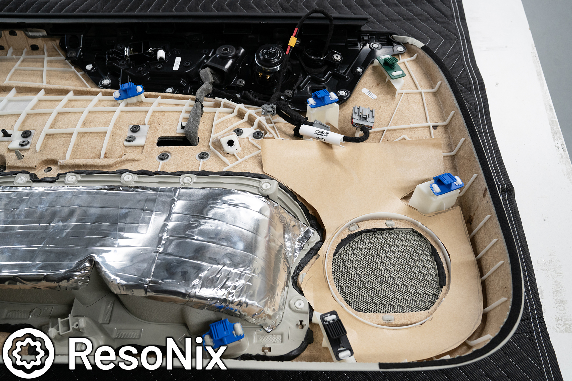
Once the midbass driver assembly was complete, the door panel was reinstalled and ready to be put back together.
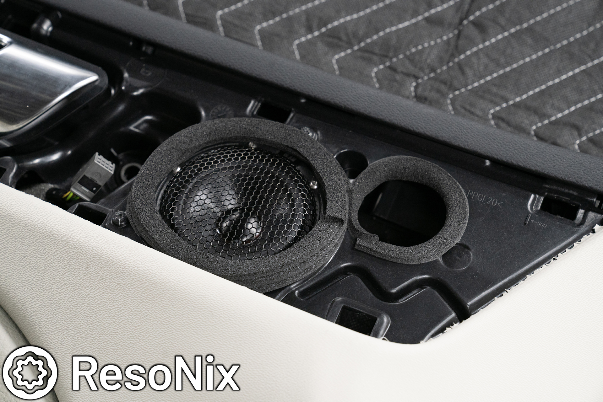
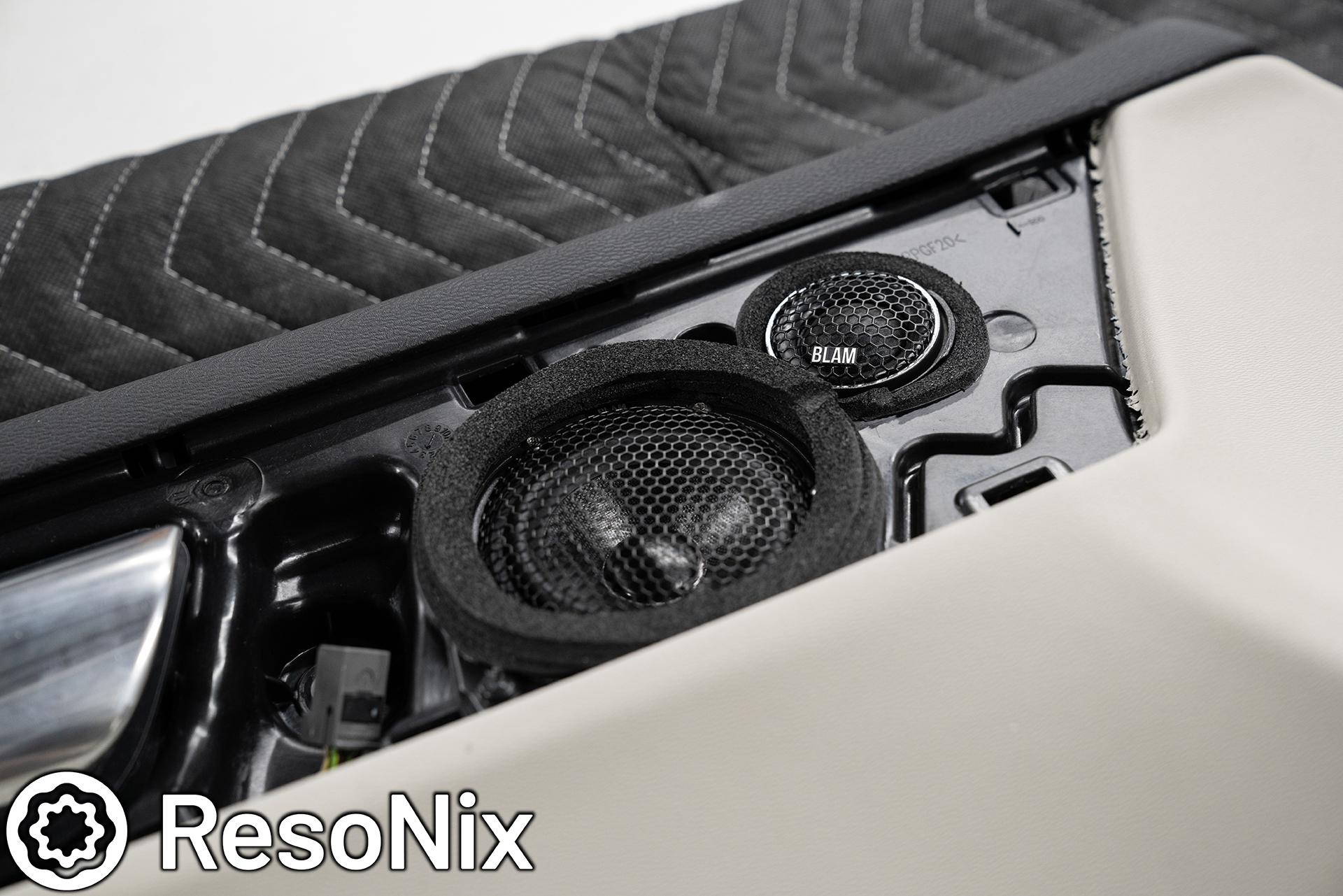
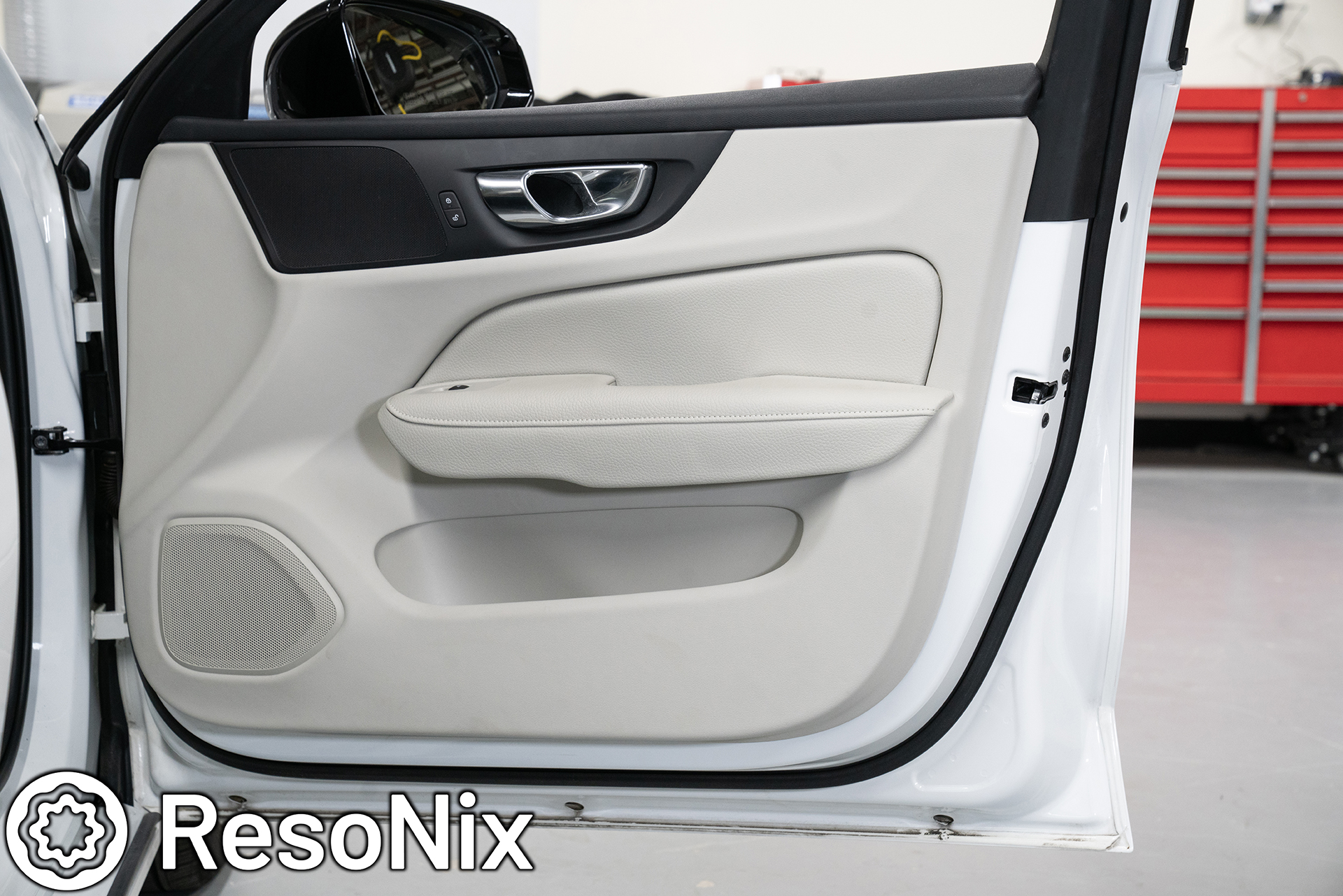
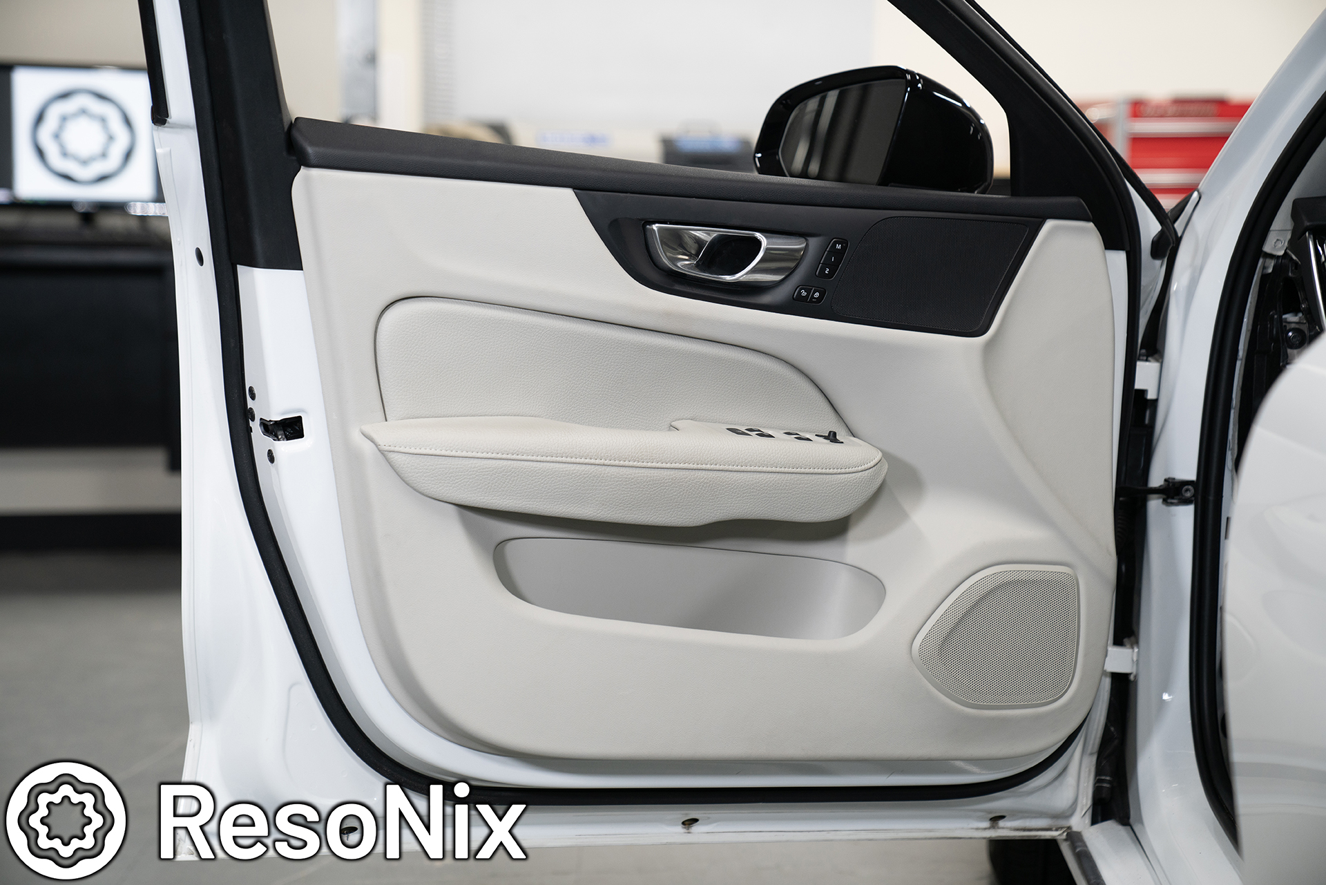
Midrange & Tweeter grille door trim reinstalled. As mentioned earlier, we stacked up enough foam around the midrange and tweeter to have them sealed to the opening, which ensures the best performance possible.
The doors are now complete.

Next up, grabbing signal. In this vehicle we would have had to grab high level signal from the factory amplifier, which works, but is always a hit in the sound quality department. You deal with the factory equalization, crossovers, all pass filters, signal delay, upmixers, compressors and limiters, as well as the distortion and overall poor sound that the usually sub-par hardware causes. Fortunately, we have a work around 🙂
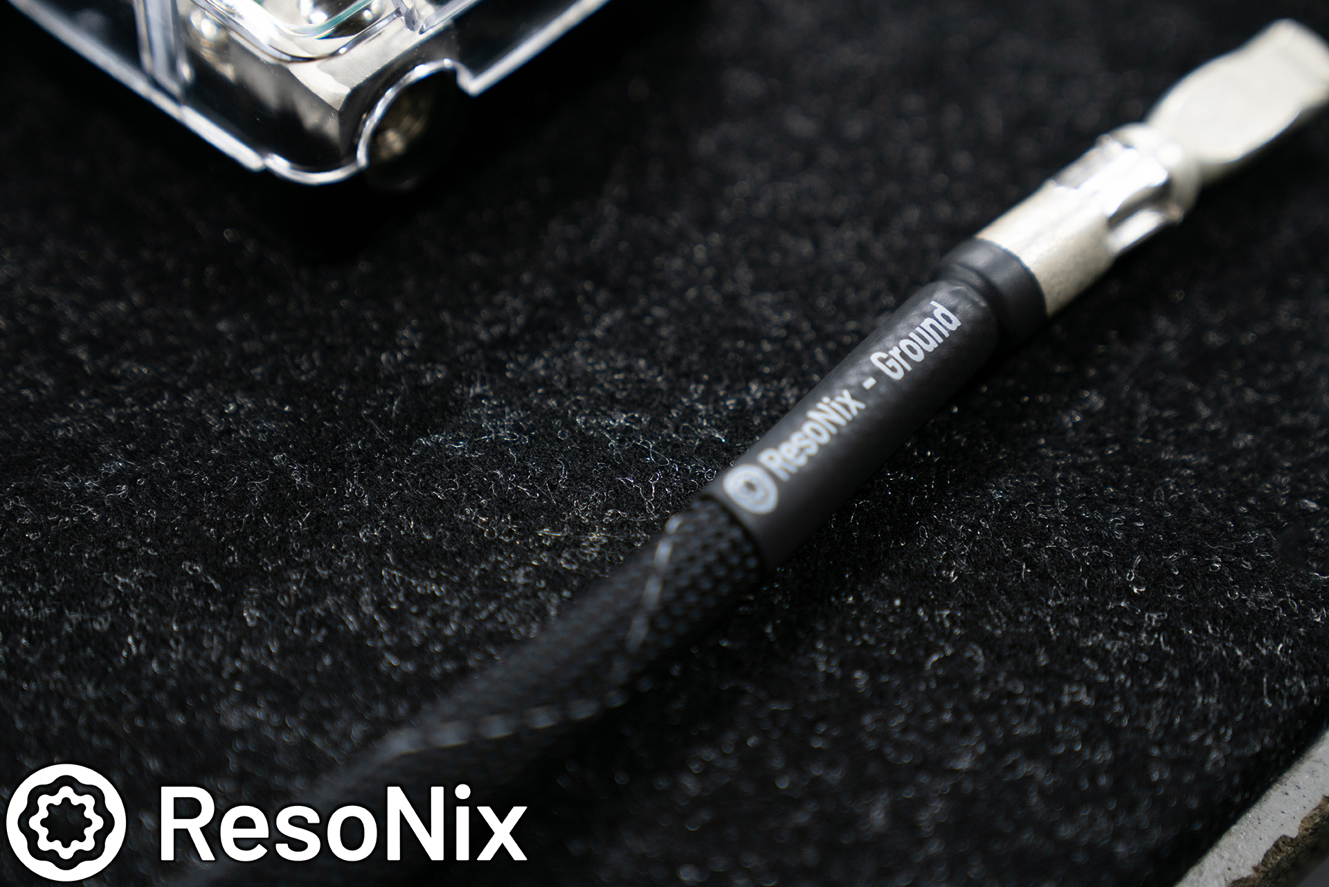
Thankfully, ResoNix has an OEM interface prototype that we used to grab the digital MOST150 signal that sends audio signal from the head unit to the OEM amplifier. This allows us to decode the signal and get perfect signal from the factory radio. While we do have another interface that works on Volvo’s, it only works up until 2020 (maybe 2021). The 2021/2022 and newer have received a facelift where the Valse Most150 that we offer does not work. This new interface on the other hand, worked flawlessly. It allowed us to take that unadulterated MOST150 signal, and convert it into optical or coaxial outputs. I opted for optical since my brain automatically thinks to run optical when doing an interface, but only later realized that since it has coax output as well, I could have just used our ResoNix Solderless Custom RCA system, which is a bit more reliable. This is actually why I run two optical cables anytime I do optical. You may be able to see an extra optical cable tucked away here.
Speaking of these interfaces, they are going to be available shortly through ResoNix, and for way more than just Volvo. BMW (yes, even the new BMW’s with Ethernet), Mercedes (yes, even the new ones with coaxial), Land Rover (yes, even the new ones with ethernet), Lexus/Toyota (select models), Cadillac (select models), VW (select models), and more. ETA: Late January 2024.
Another little teaser… compared to other units on the market, pricing will be competitive 🙂
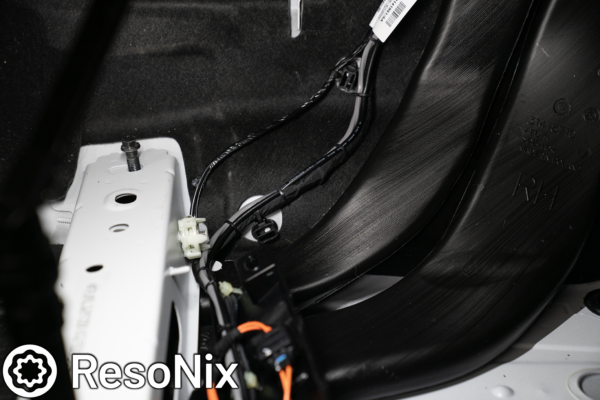
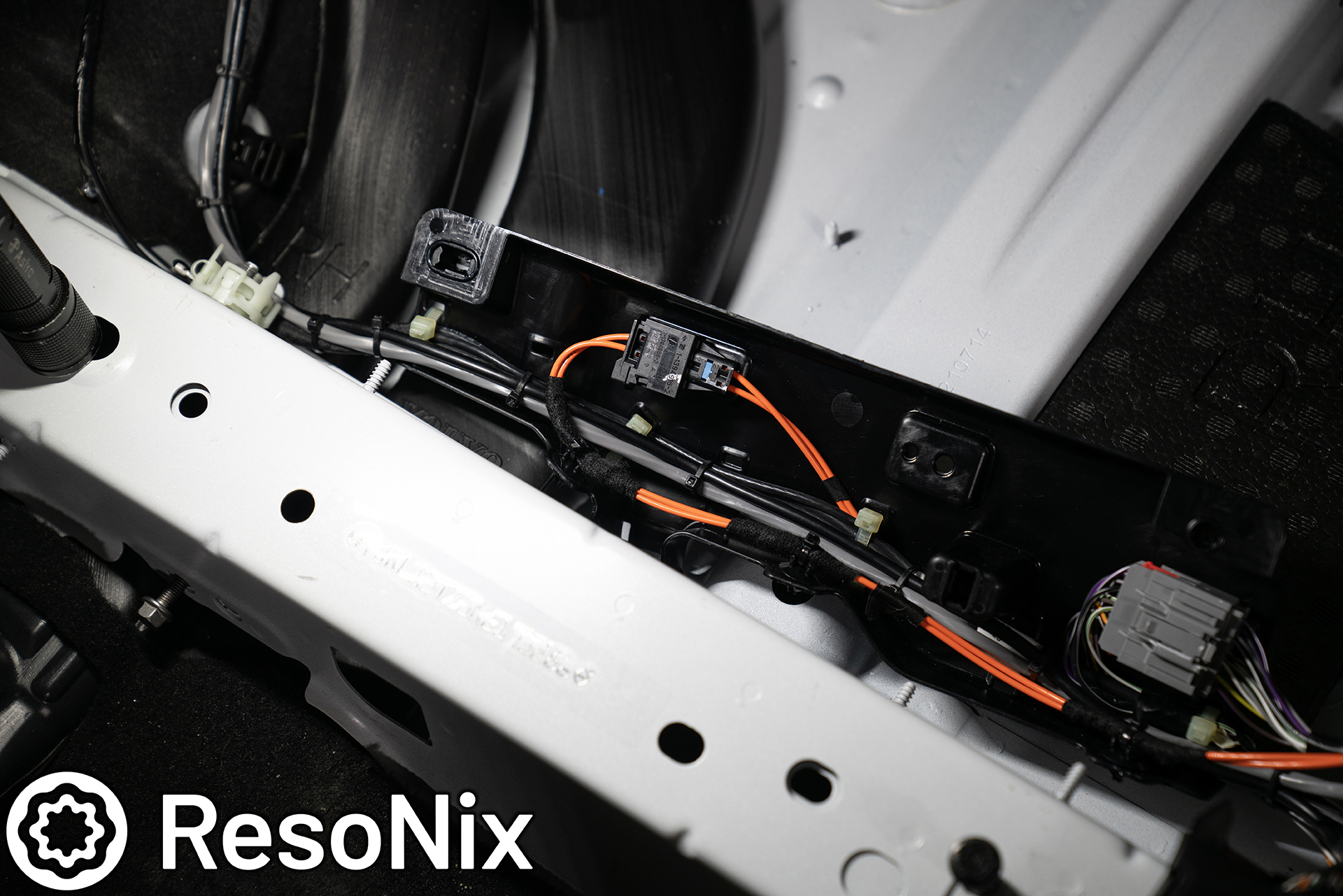
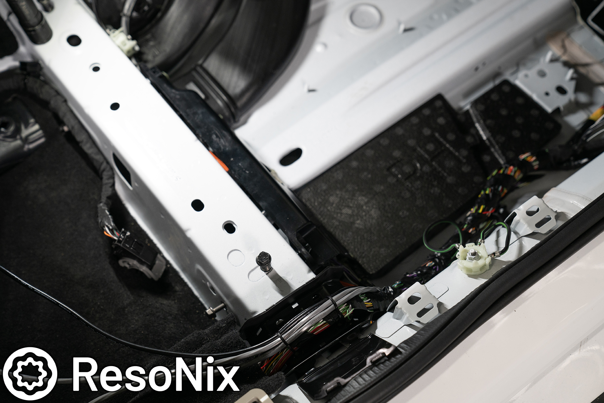
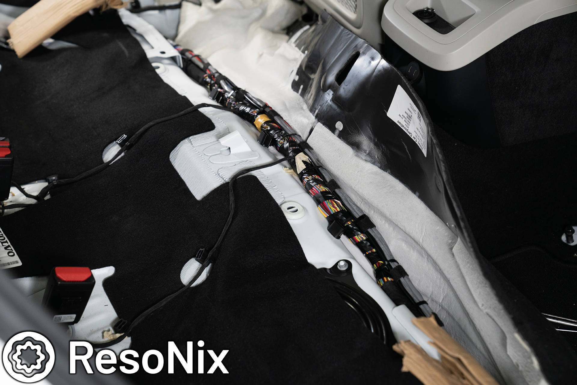
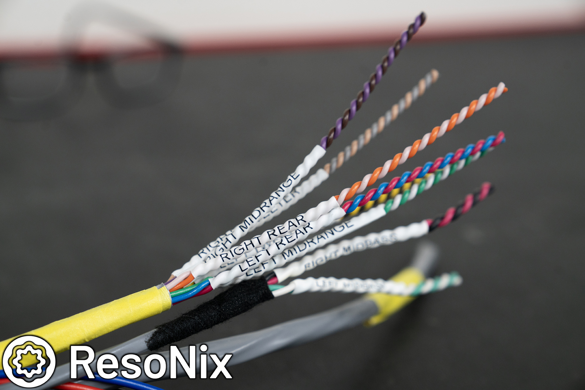
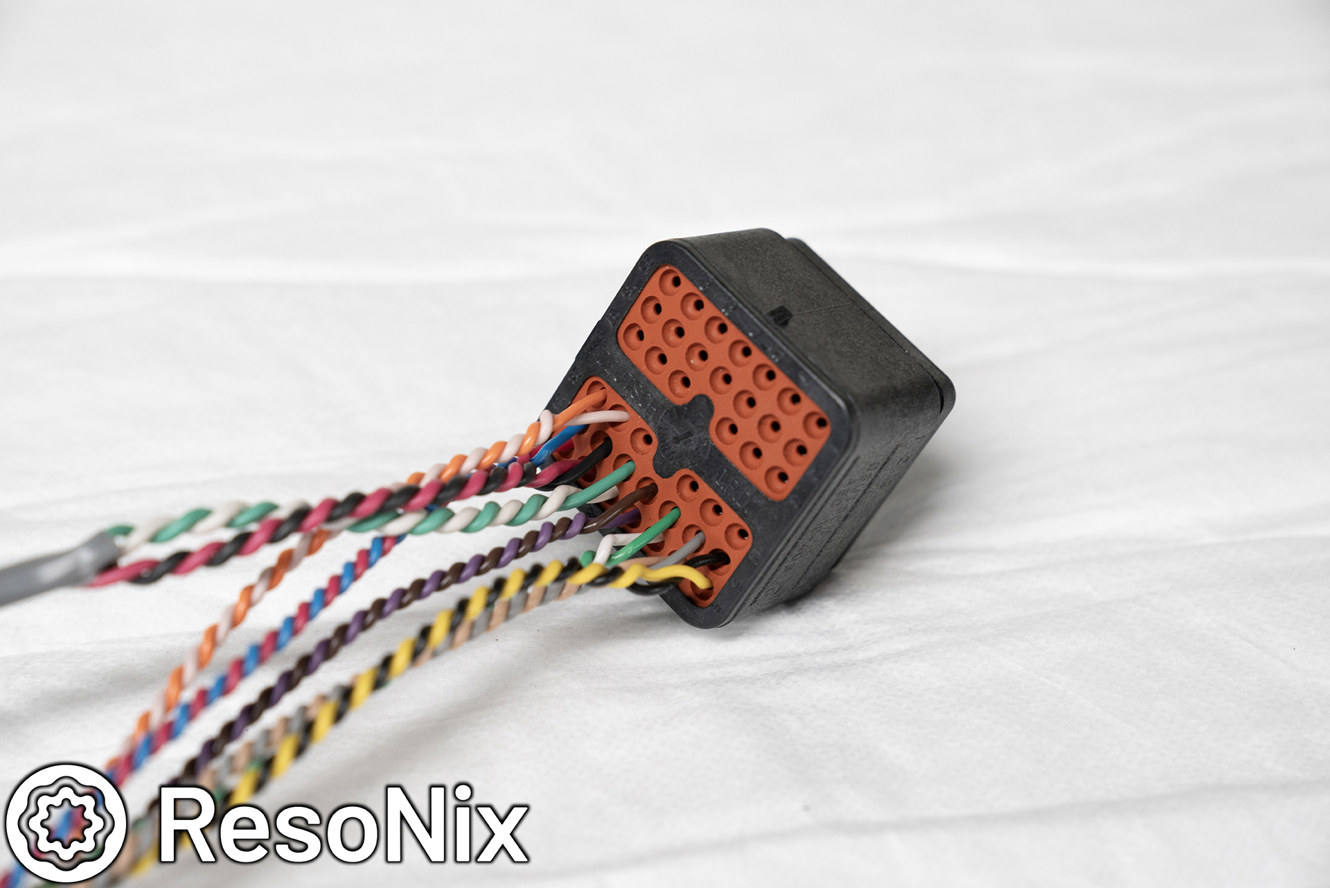
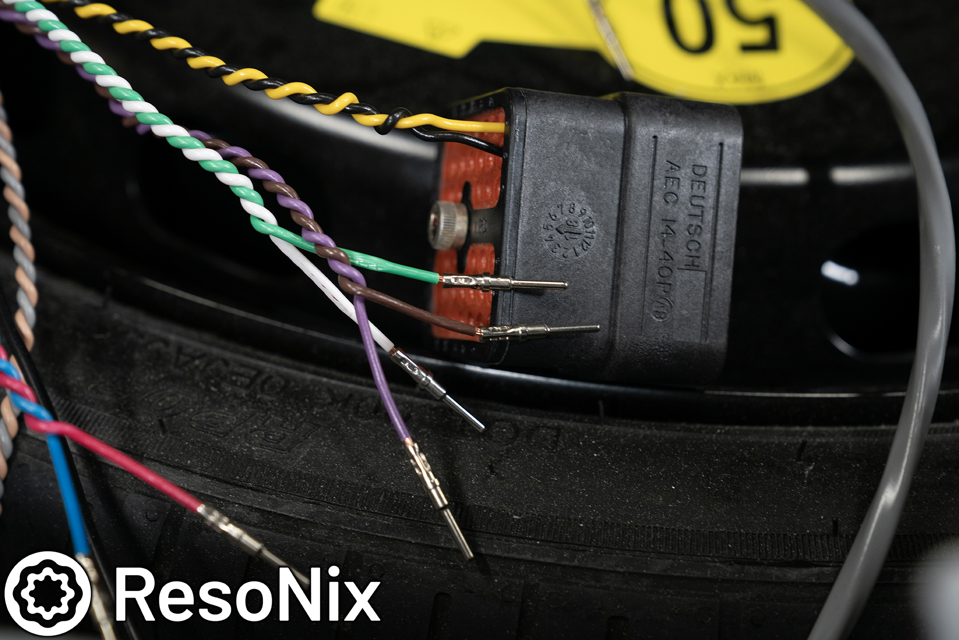
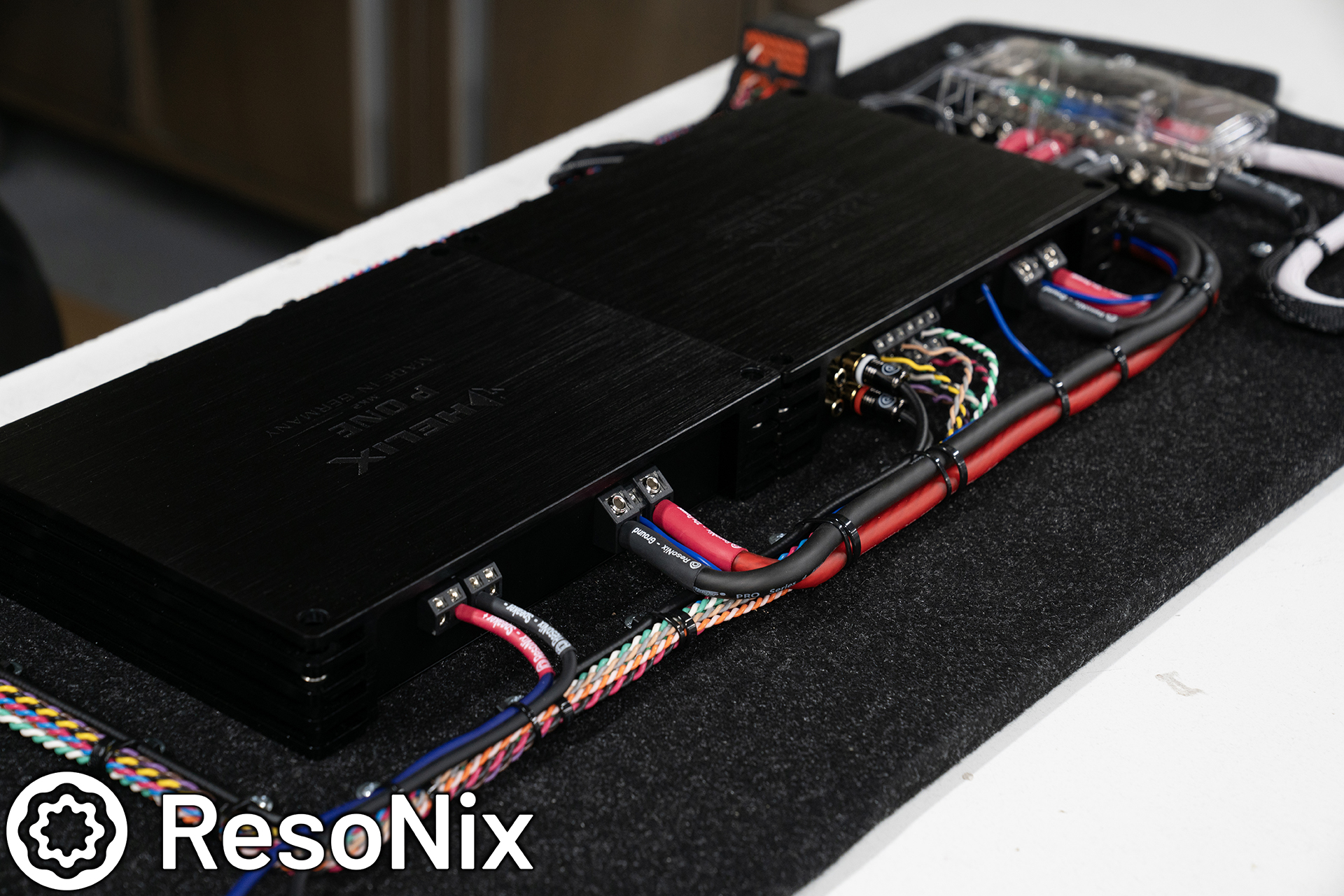
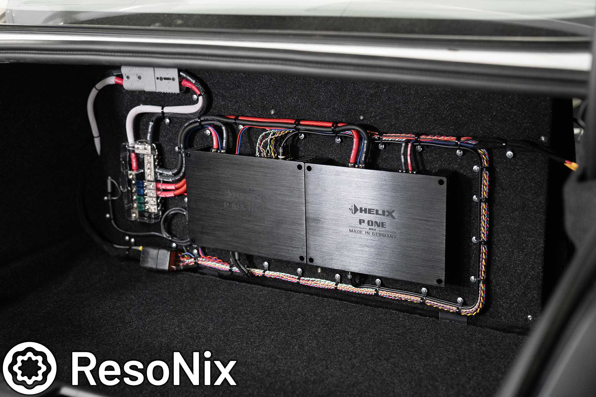
Up next is the wiring. All of the wiring from the speakers, the Helix Conductor, as well as power, ground, and remote out, and optical outputs for the interface, and even a few extra wires just in case are routed very cleanly and carefully down the passenger side of the vehicle, and across the back seat. All of it follows along the OEM wire harness and is zip tied every 4~ inches.
The passenger side midbass speaker wire run down the passenger side.
Once they were run down the passenger side, they were run across the front of the rear seats.
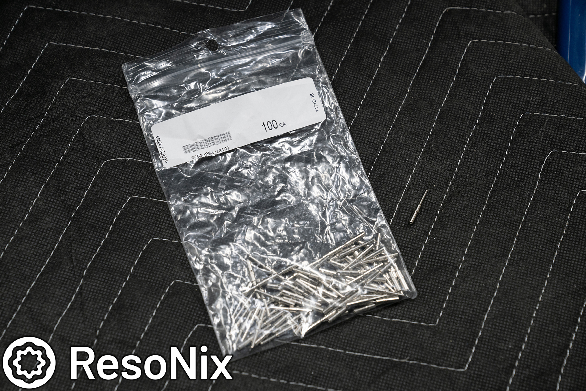
EVERY single wire that was ran to the back was terminated in an easy to remove and impossible to mess up way. For the speaker wires, power/ground/remote out for the interface, and conductor, they were ran into a Deutsch connector with 40 slots for easy servicing and removing of the amplifier rack. This was more than enough slots for the wires we had at hand, but why have more than needed? Again, planning and keeping the possibility of issues in mind. Experience shows that while I may be able to do a perfect install, and the interface we are using may be perfect in any way, one day Volvo might come out with an over-the-air update that renders that interface inoperable with their new update. So always planning ahead, I also ran high-level input wires just in case. I tested the interface before doing any of this, so I knew that it worked out of the gate, but we do have a plan b just in case Volvo changes something. This isn’t unheard of, so I planned ahead for it.
These Deutsch Connectors arent your average connector. Weather sealed, high current, and easily servicable. They make for an awesome solution, but come with a very high price. This connector set and all of the pins run about $300, and the specific crimpers for it, another $60 for the pins of this size. Expensive, but worth it for these situations. This, along with some of the other things I implemented, allow the amplifier rack to be fully removable in less than 5 minutes.
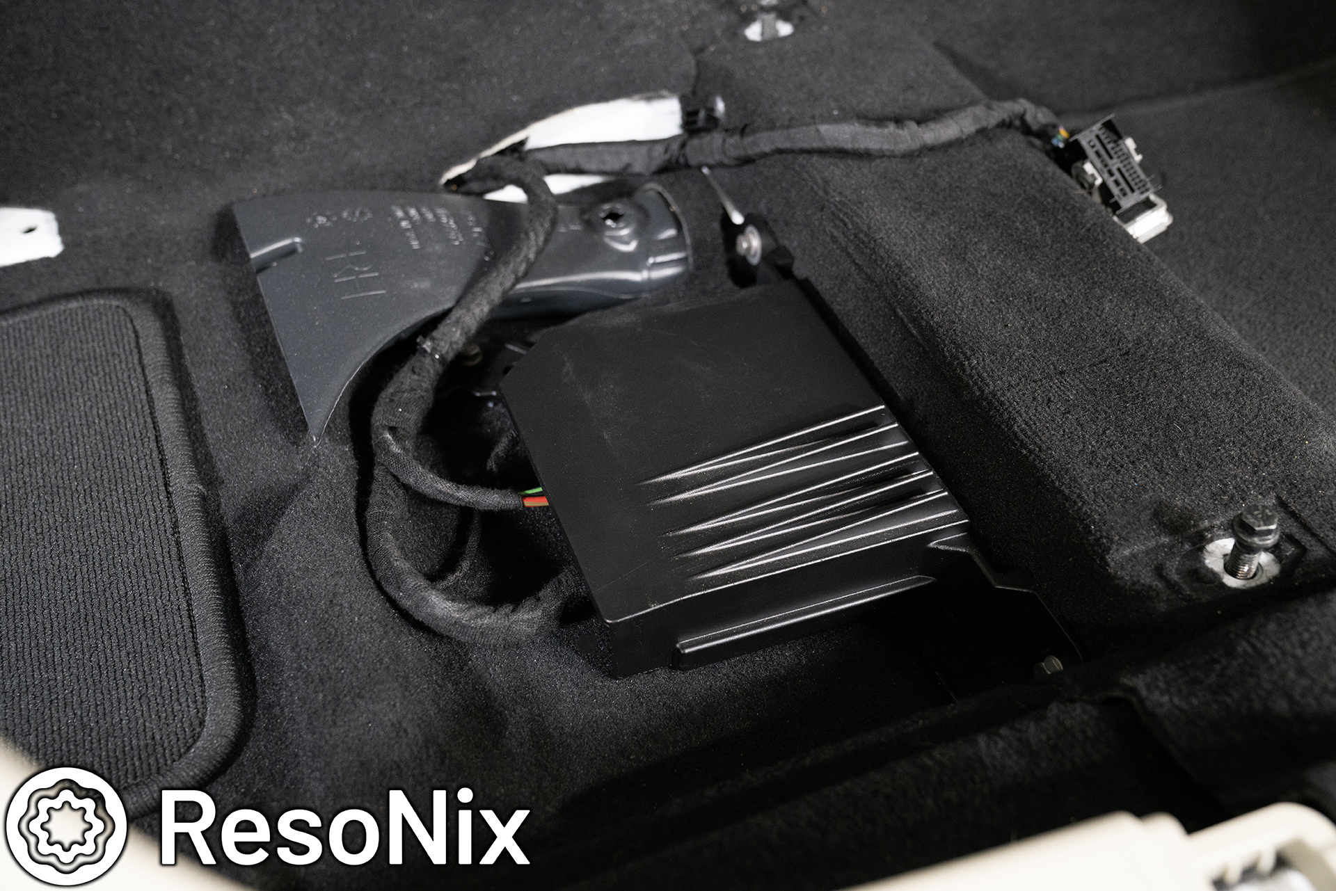
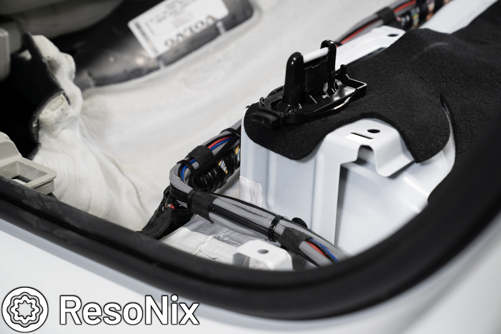
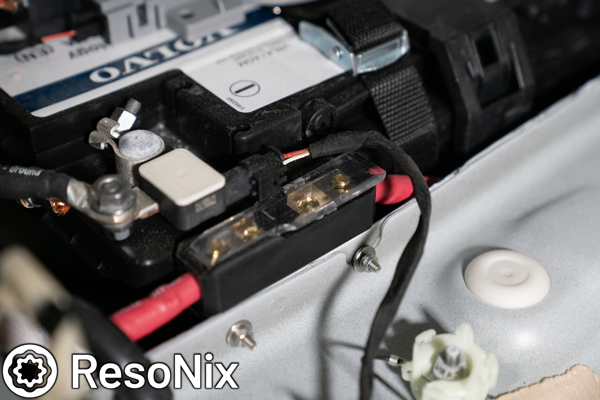
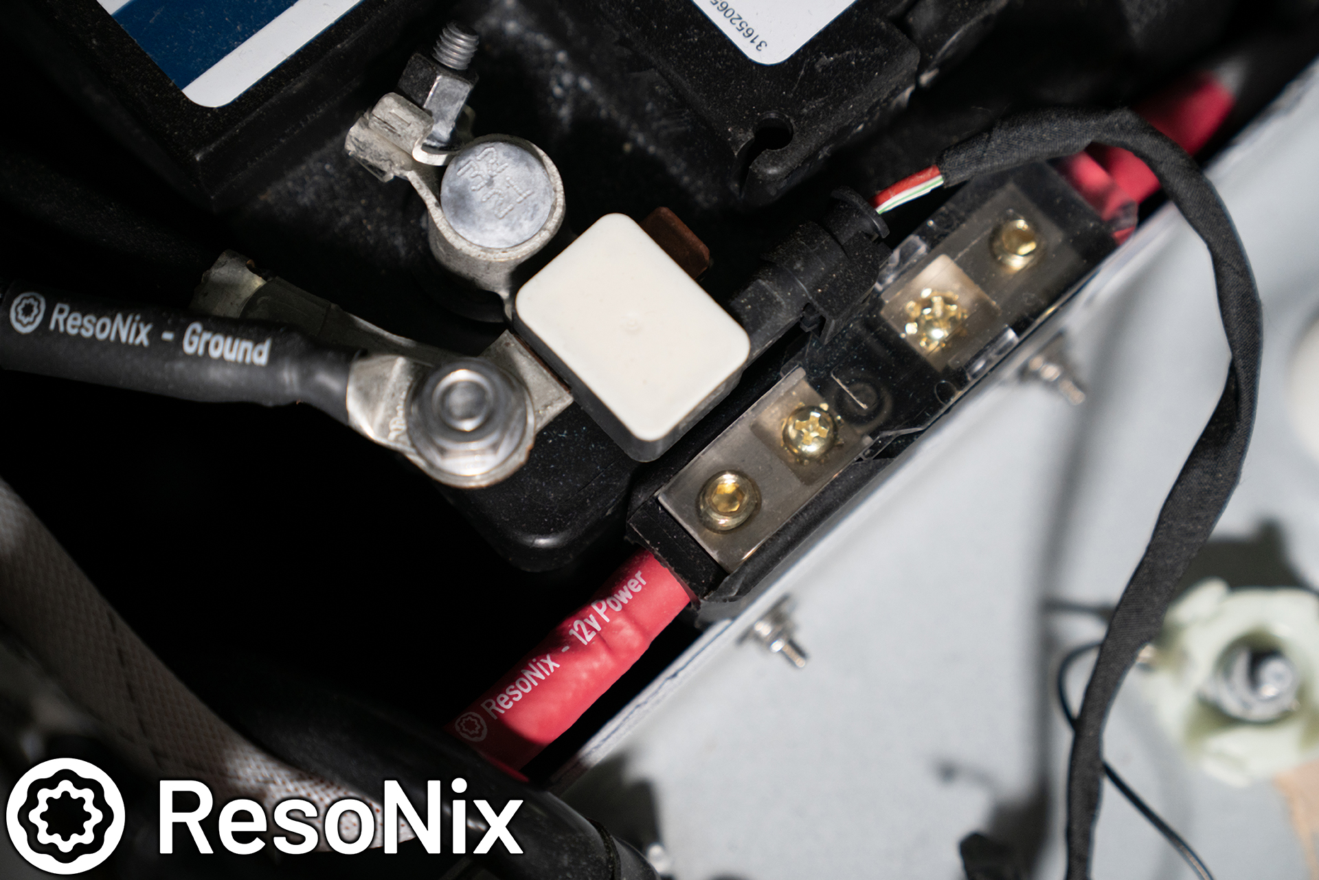
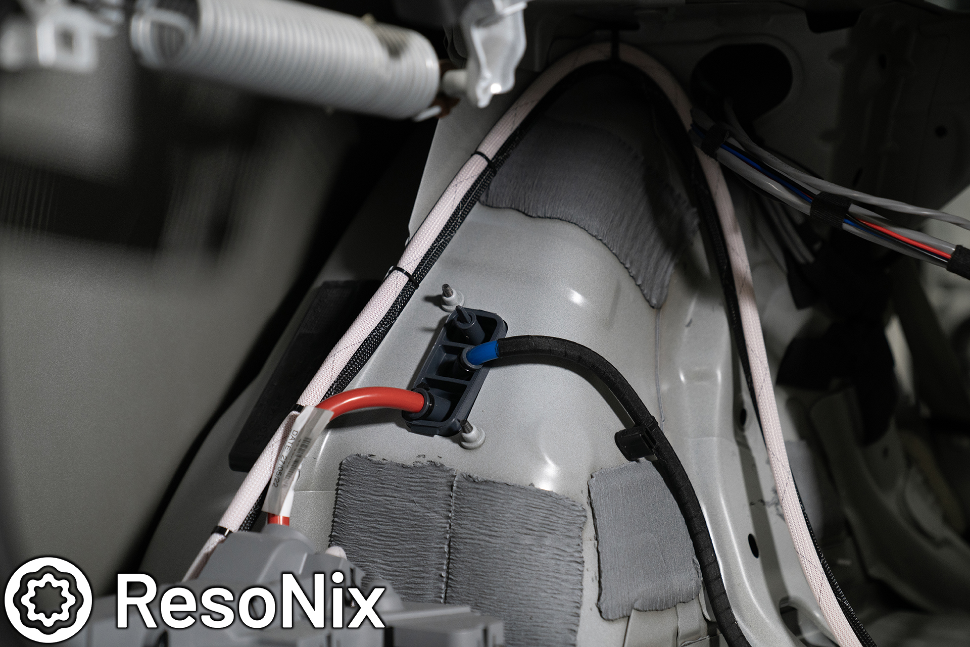
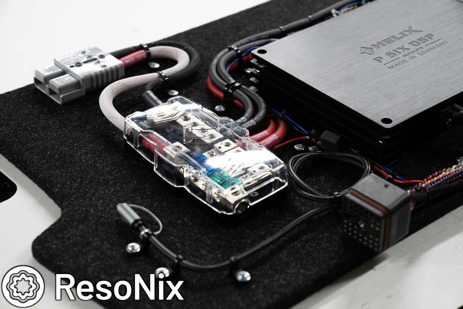
Moving on from the wire harness bundle, we have the main power wire and fuse holder. The fuse holder is located right next to the battery, and is easily serviced by popping up the battery cover. The fuse holder resides on a right angled bracket that is bolted to the car. The fuse holder is a very small design in which the cover easily slides off when needed. You can see it partially slid off in this photo.
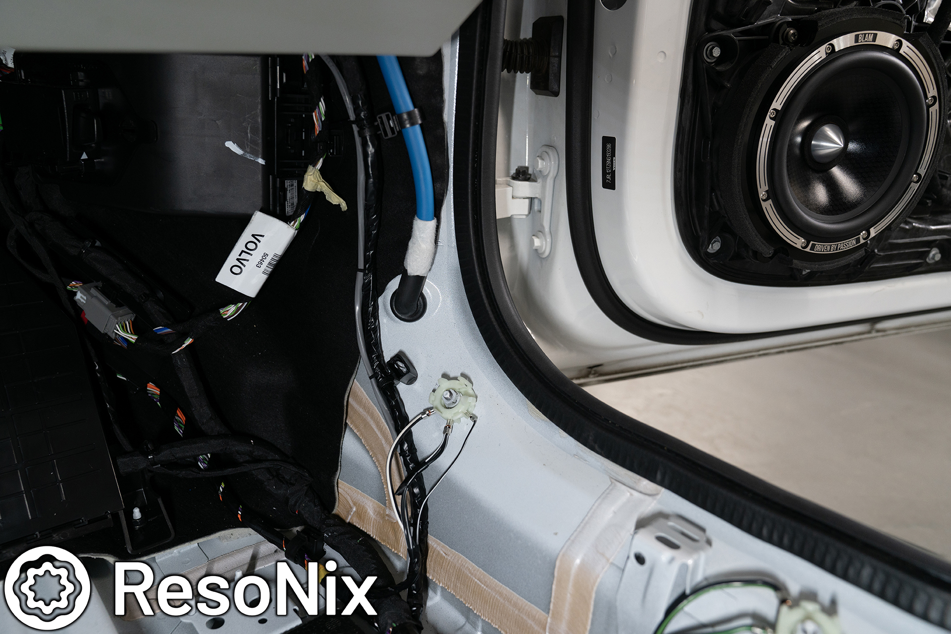
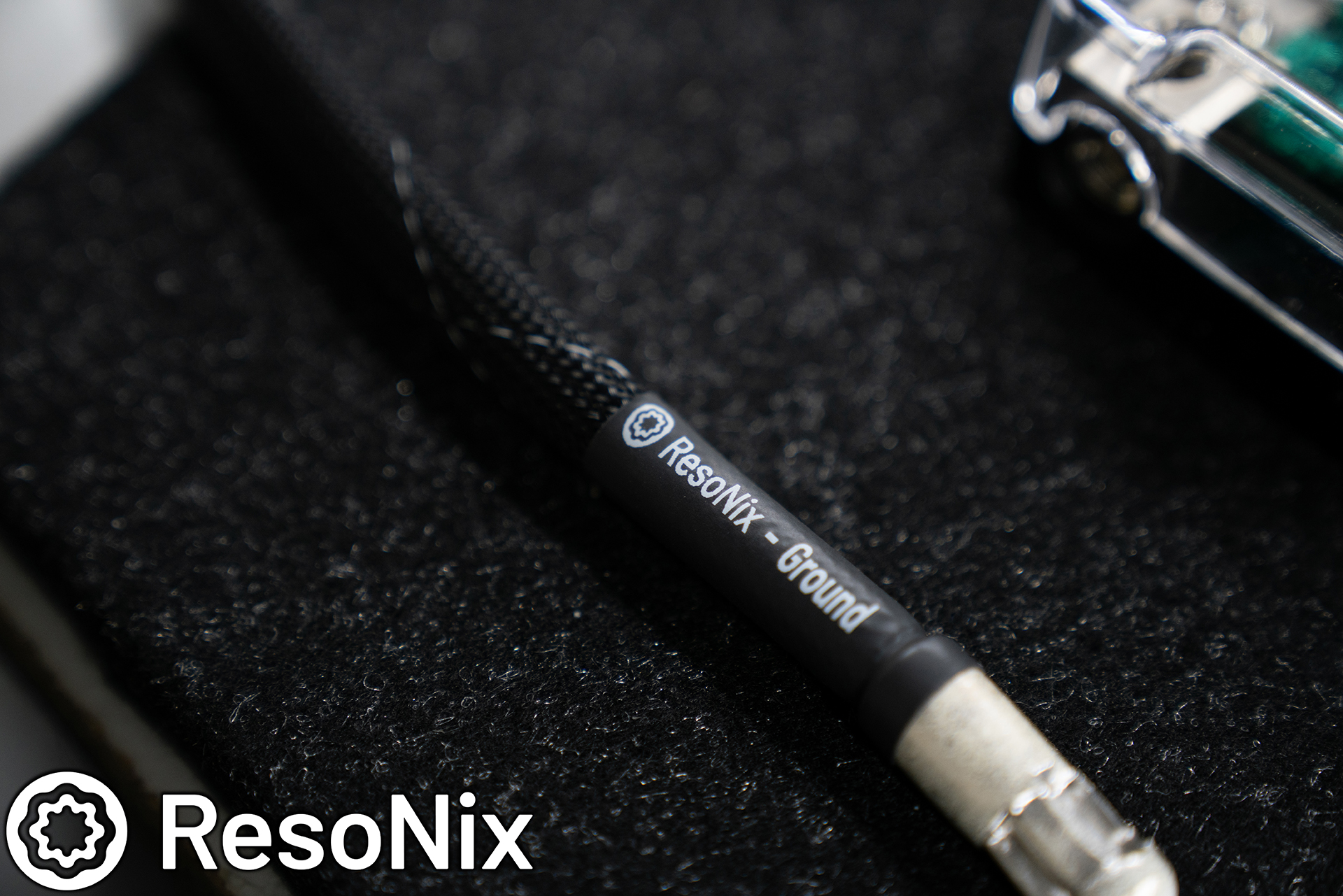
The main power and ground wires were dressed in flame retardant tech flex and run up to the rear drivers side corner of the trunk, where it would be able to pop over the top of the OEM trim, but be hidden behind the amplifier rack cover panel that we build. These were terminated with an Anderson connector, so it can be easily removed from the amplifier rack for again, easy serviceability for parts that may need to be serviced. Again, any parts that I deemed not serviceable by anyone not qualified were dealt with using tamper resistant screws.
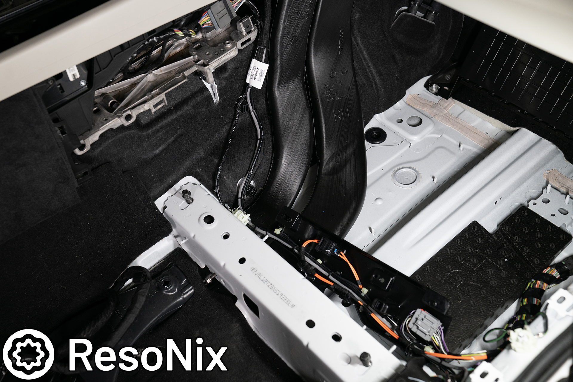
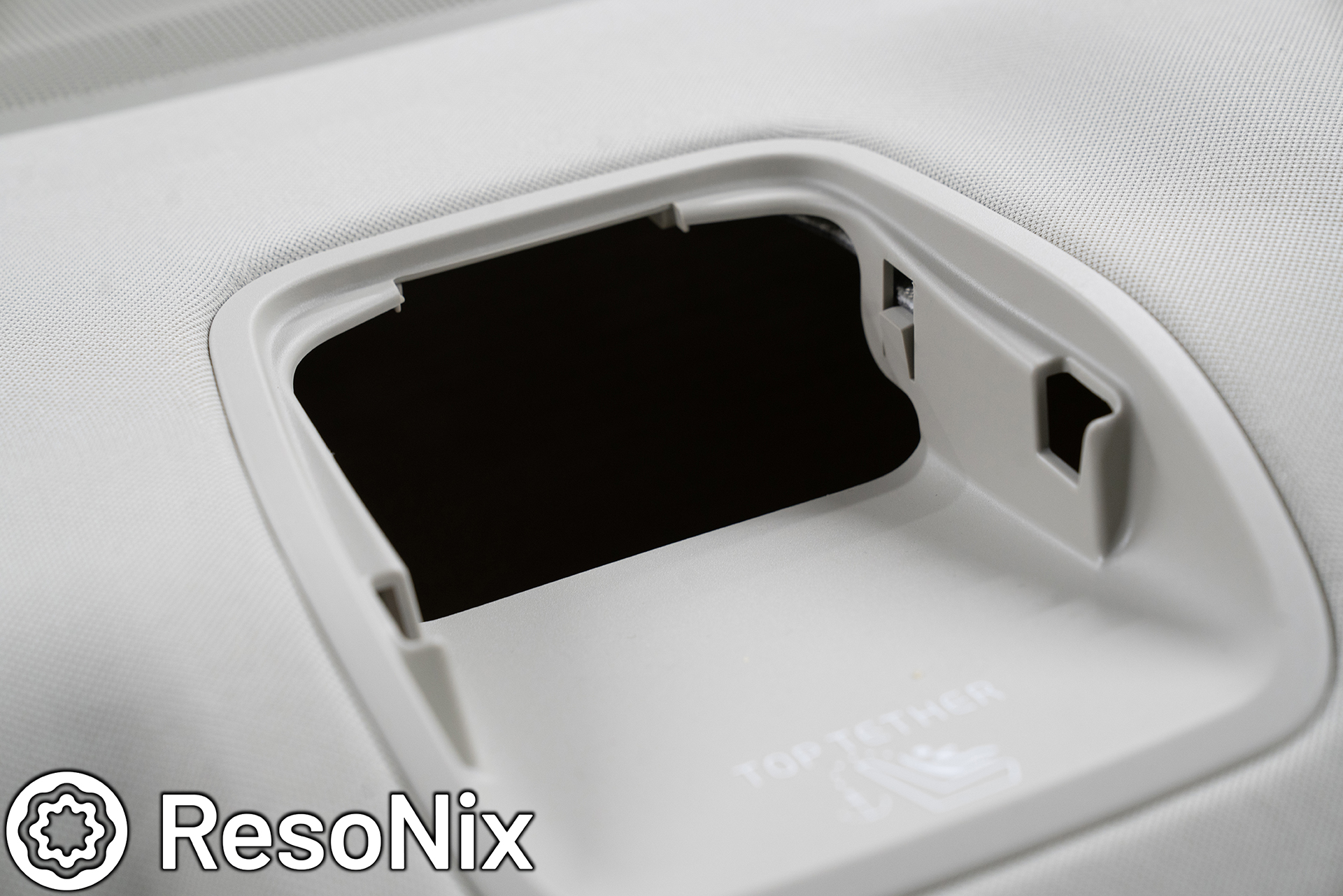
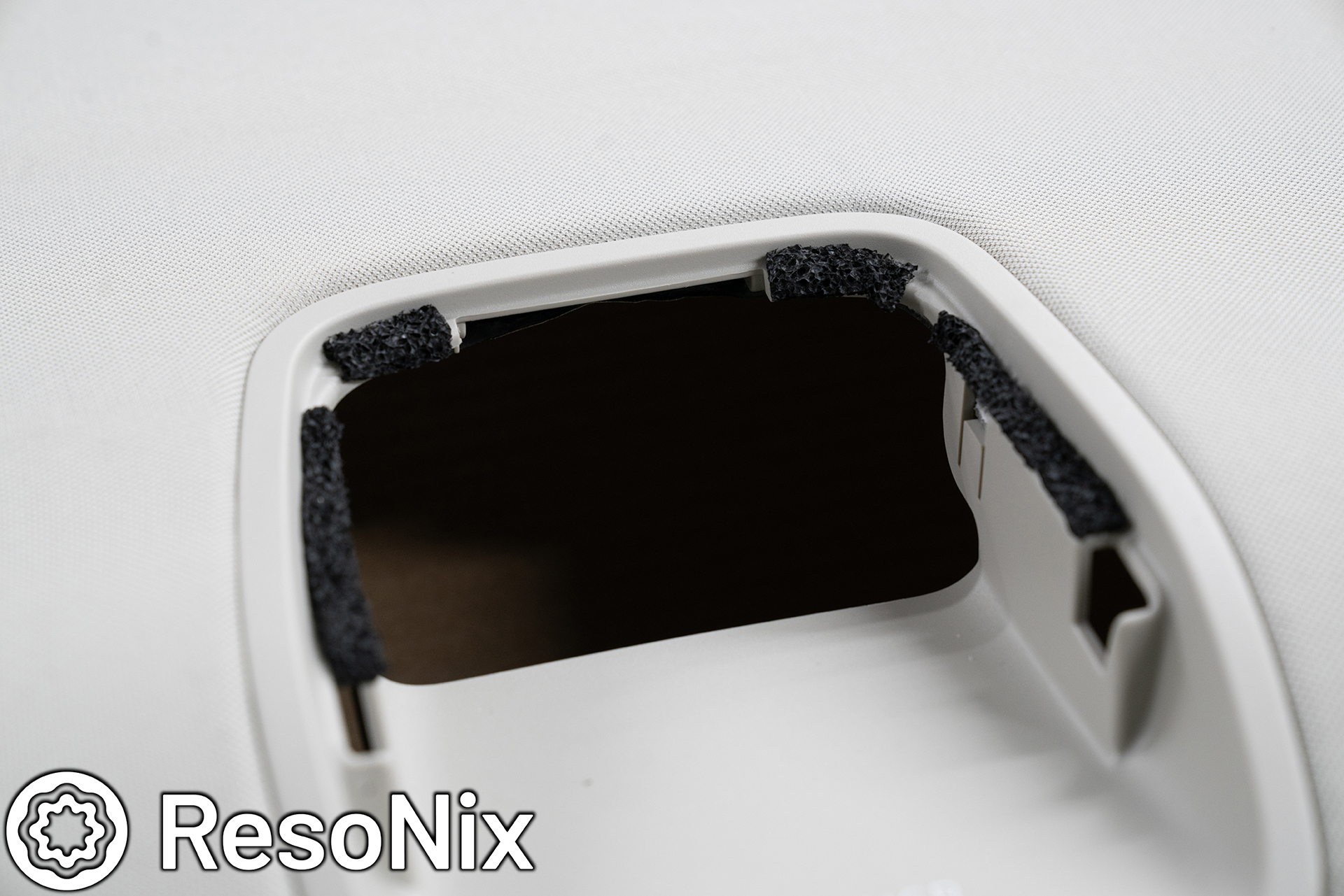
While we ran the wiring, the B-pillars had to be removed, which was perfect, because they are a nightmare when it comes to rattles in this car. I ended up treating them with ResoNix CLD Squares and ResoNix Butyl Rope. I spoke to the owner of this car about doing this before hand and received his permission. The upside, as mentioned, no rattles in the B-Pillar right next to your ear. The downside, I have to permanently affix the height adjustment of the seat belt, since this is the mechanism that rattles like no ones business. When the owner dropped the car off, I marked where his seating position was, where his seat belt height was adjusted to, and marked/taped it all in place so it it was set up correctly for him.
Looking at this and the following photos, you can see the many areas where small pieces of plastic are free to move and do as they please, and being in close proximity to each other is just a nightmare of rattles waiting to happen.
I first started with a piece of ResoNix CLD Squares on the body of the B-Pillar to reduce resonance as a whole from the structure. Then I moved on to using ResoNix Butyl Rope where any small plastic panels may have the opportunity to vibrate against each other. As mentioned, the only down side of this is that it holds the seat belt height adjustment mechanism in place.
The HVAC vent that resides in the back of the B-Pillar that fires at rear passengers is also a rattle hazard. I used ResoNix Butyl Rope to handle this as well.
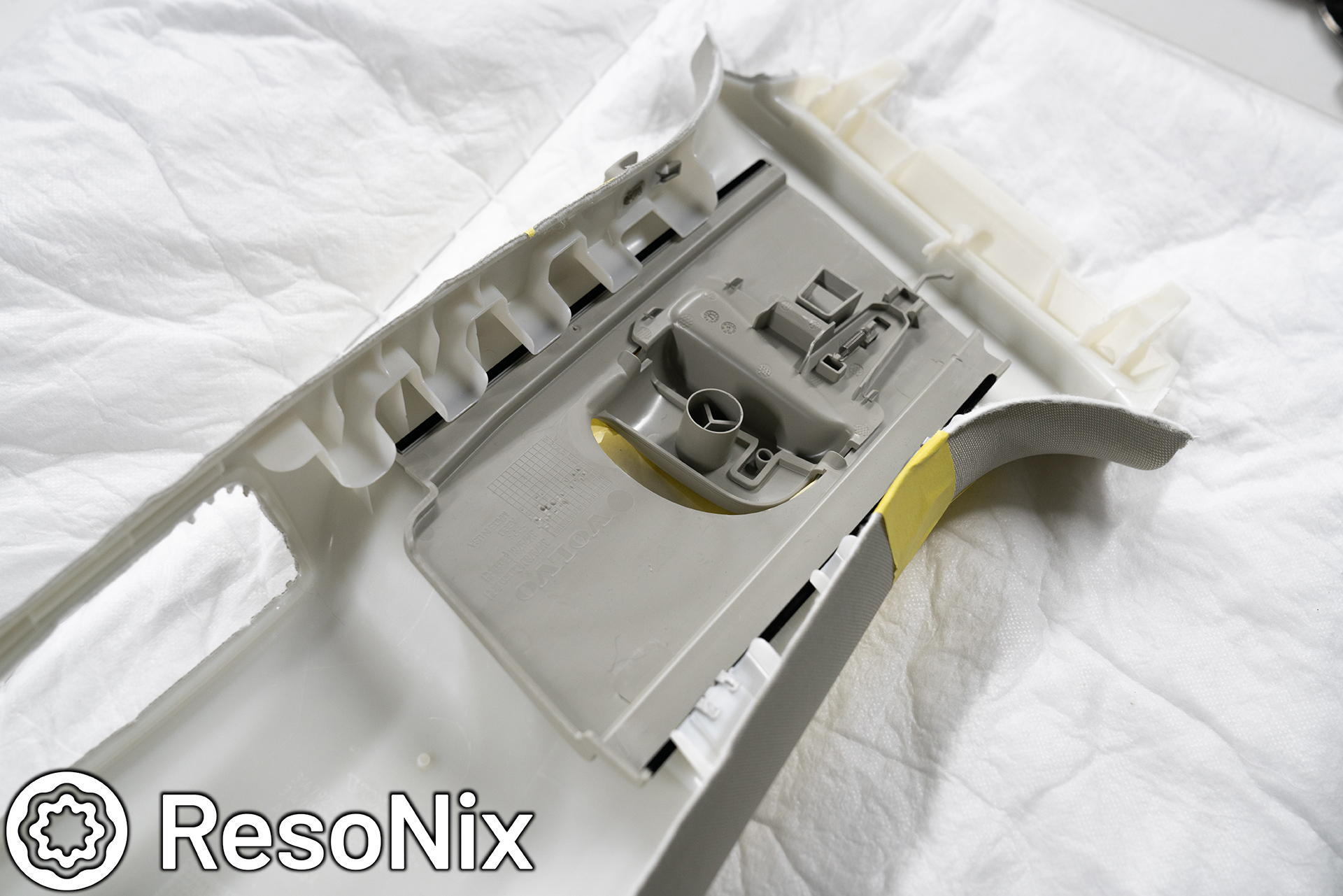
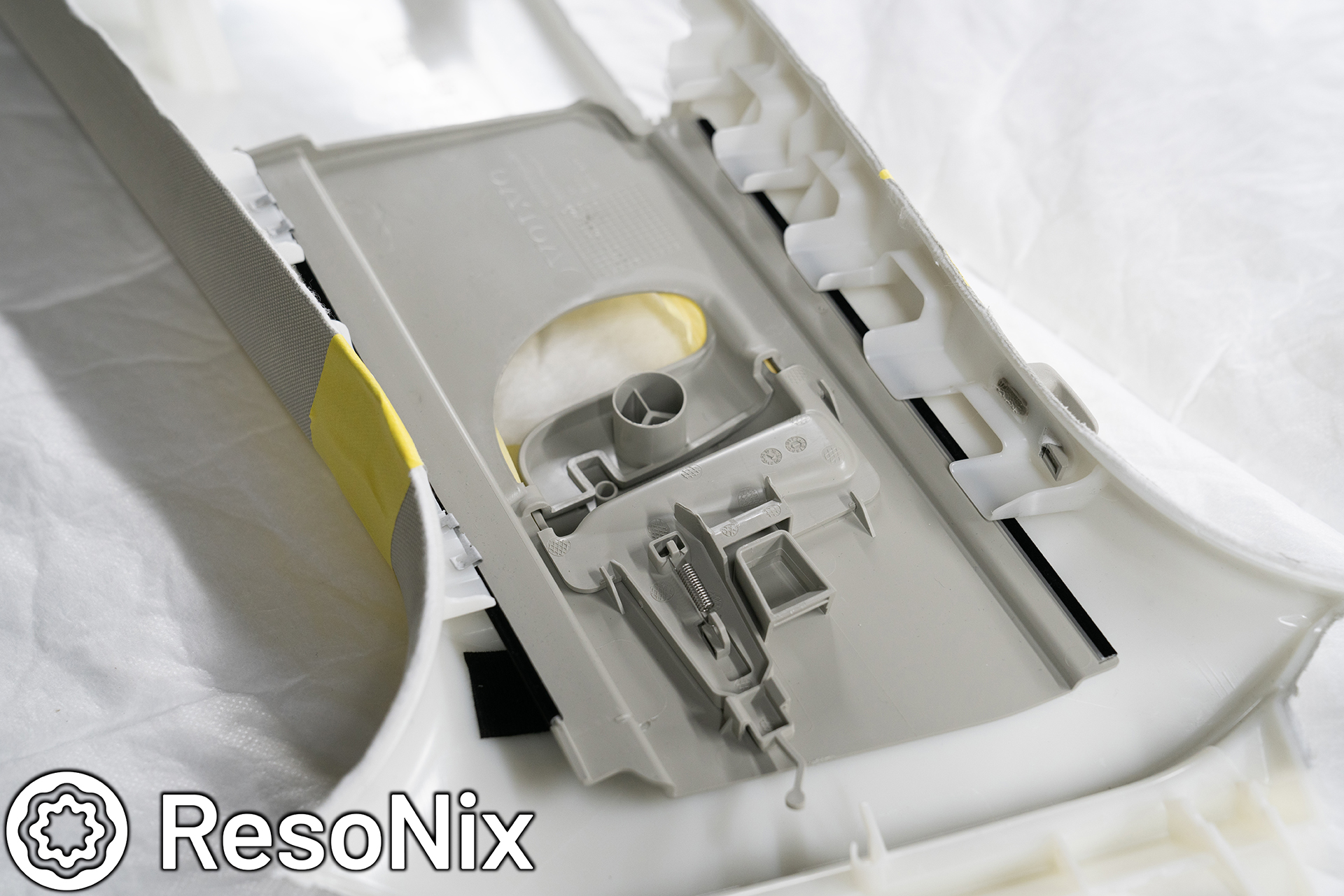
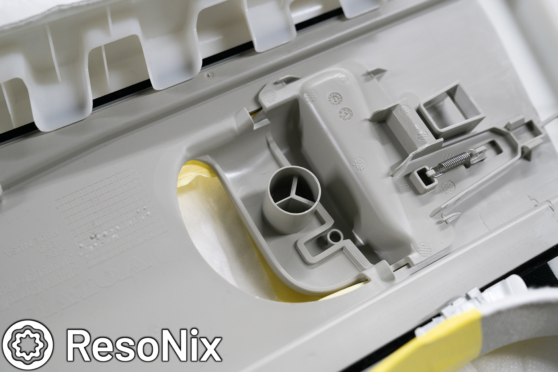
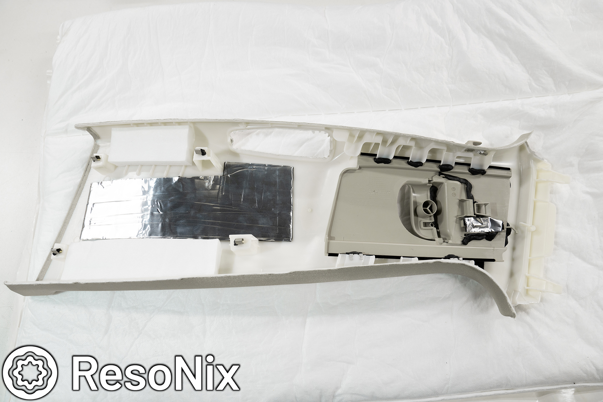
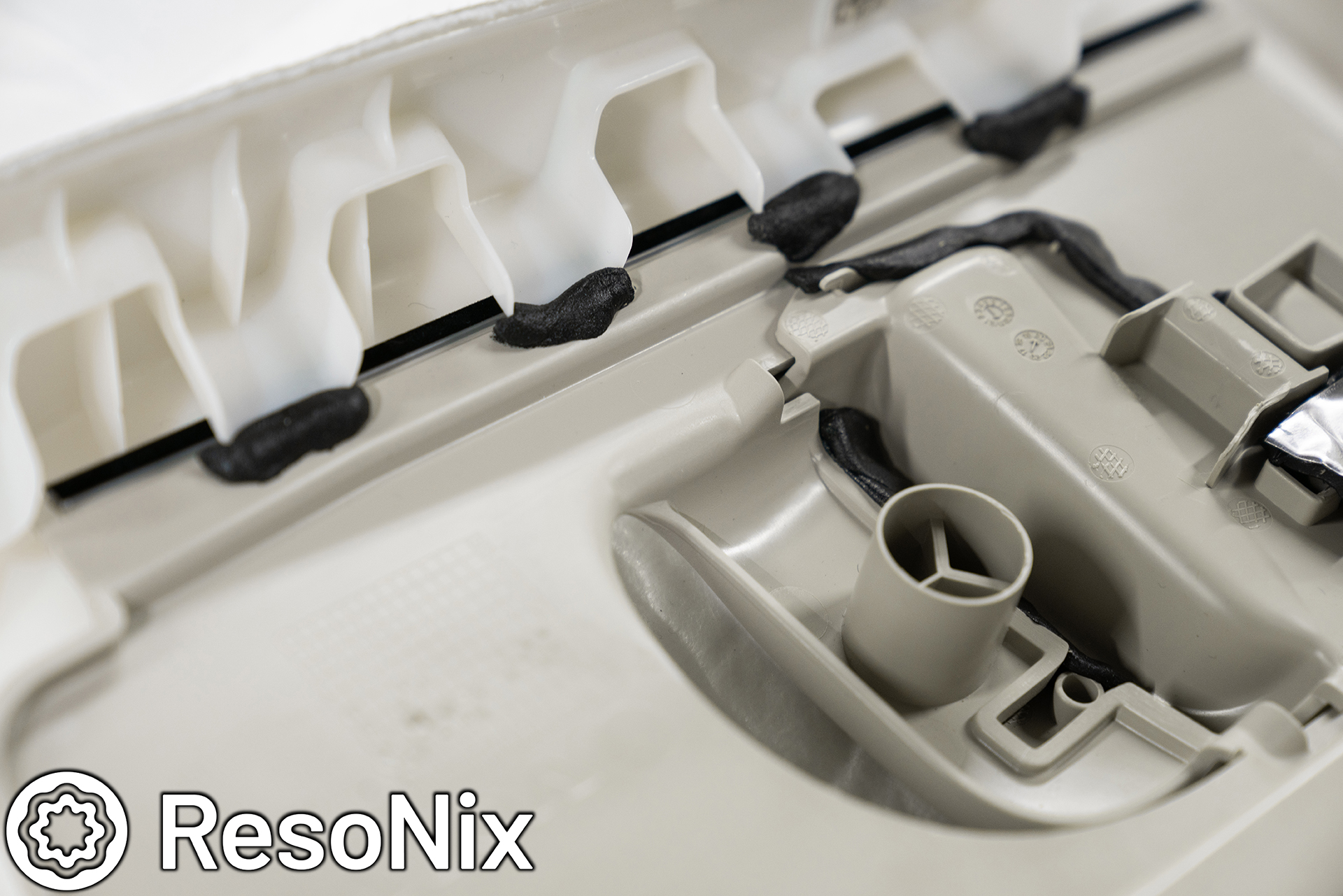
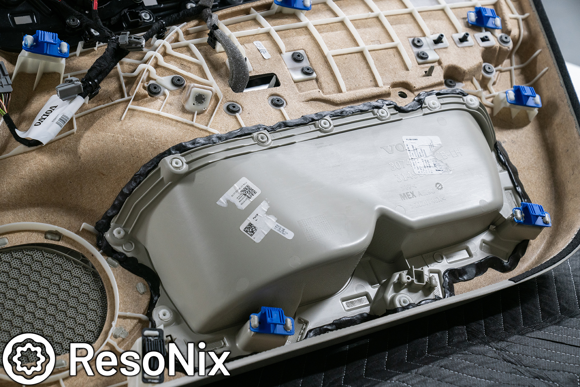
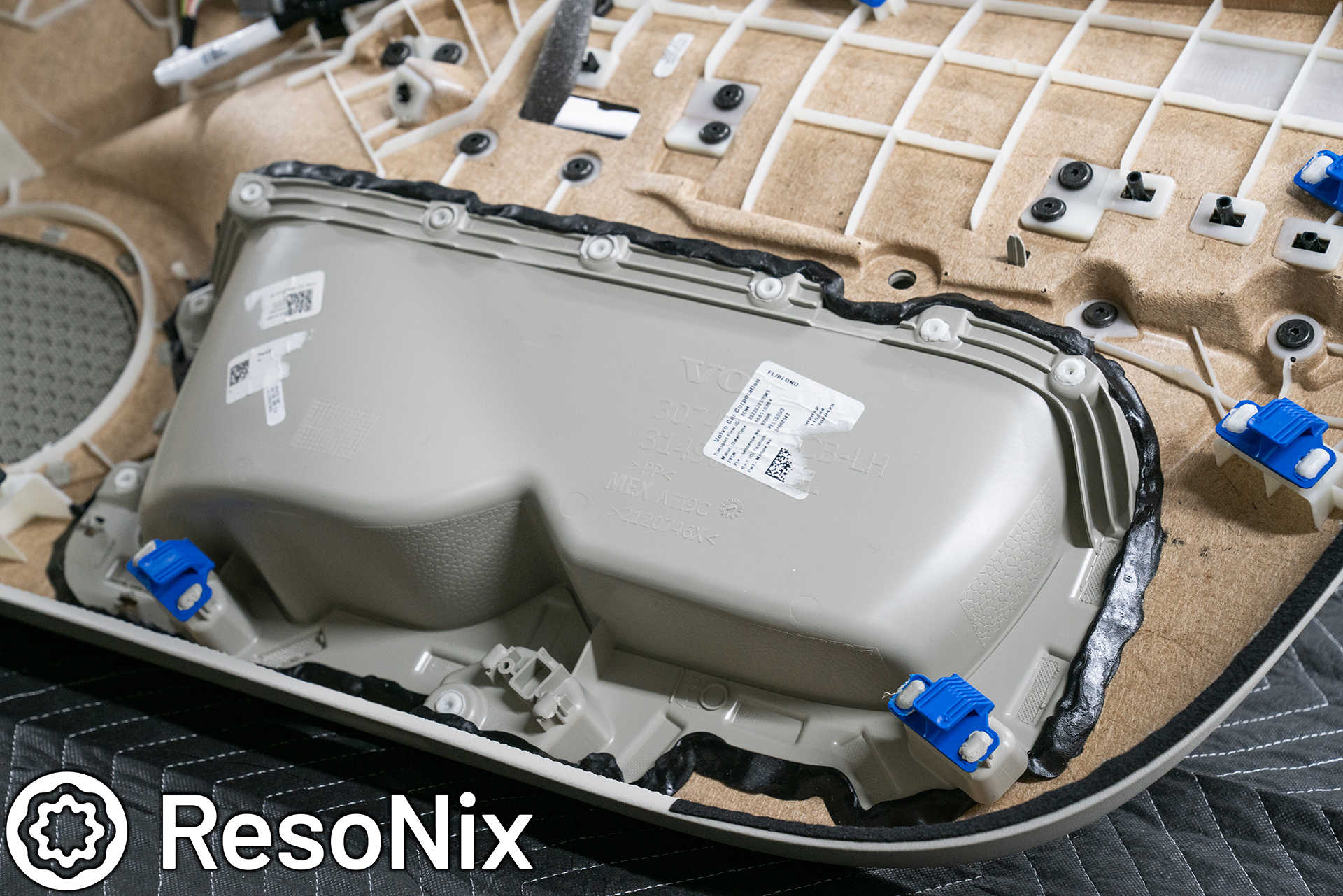
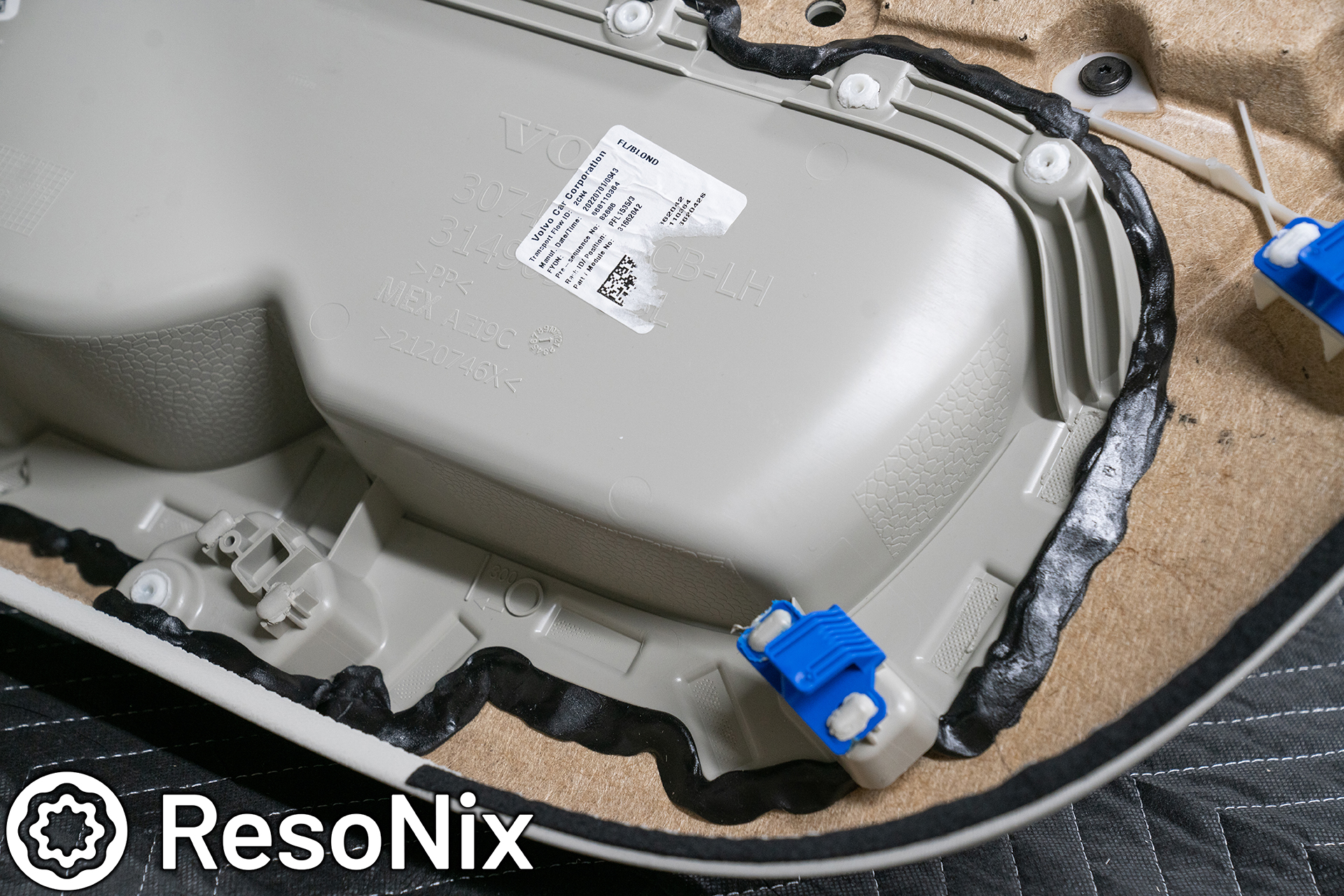
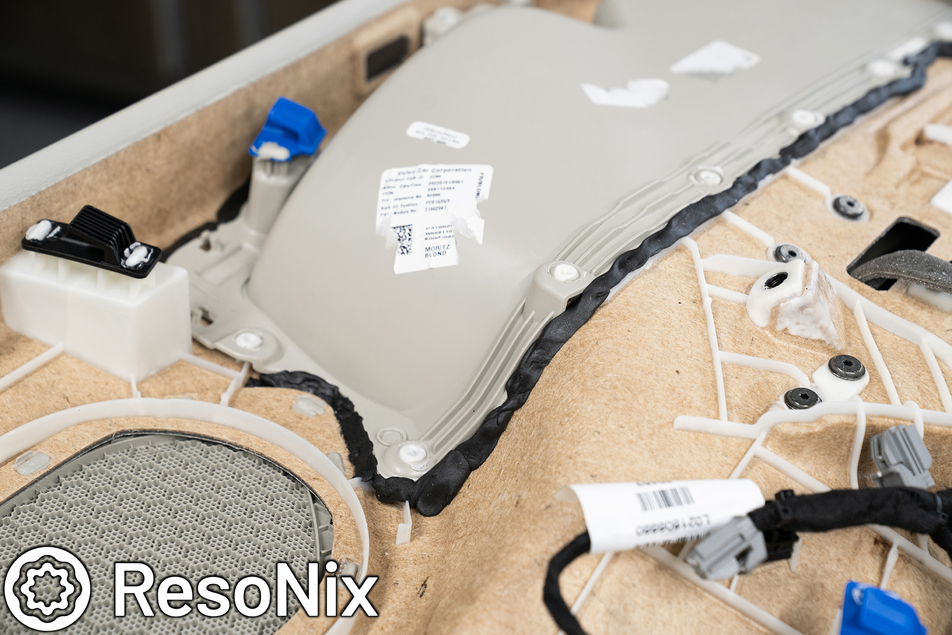
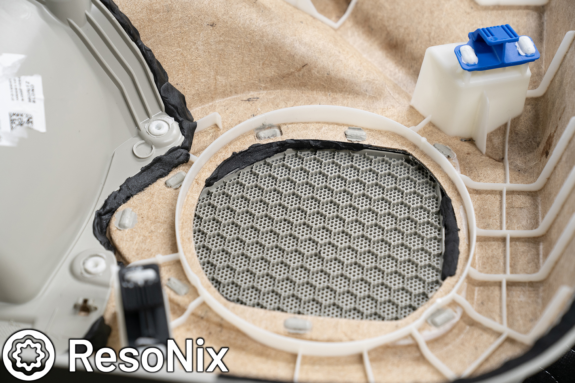
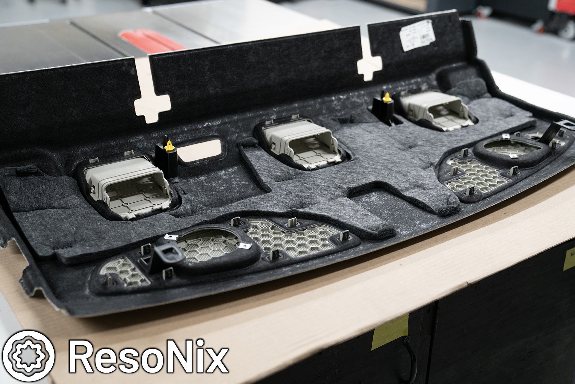
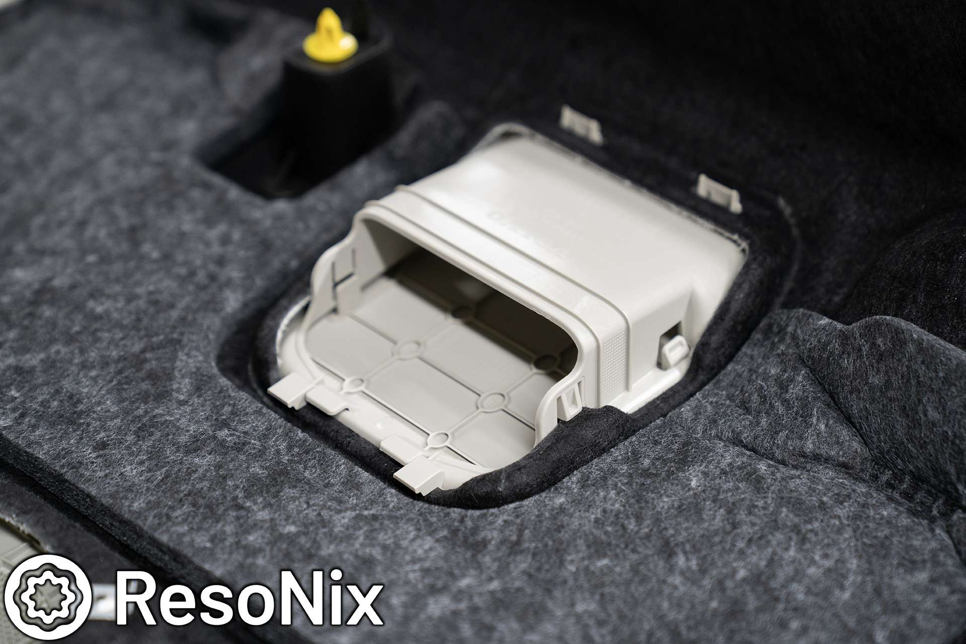
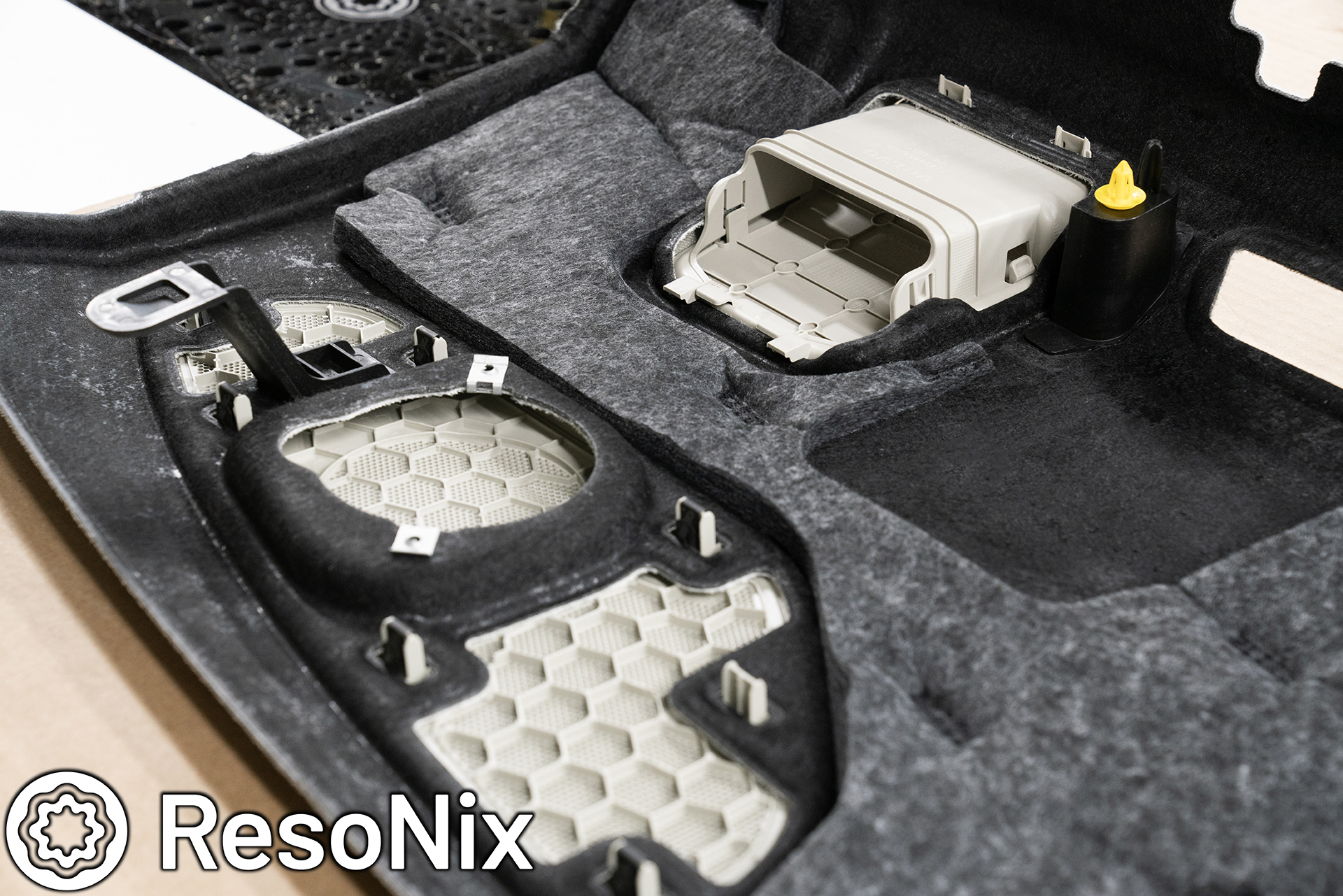
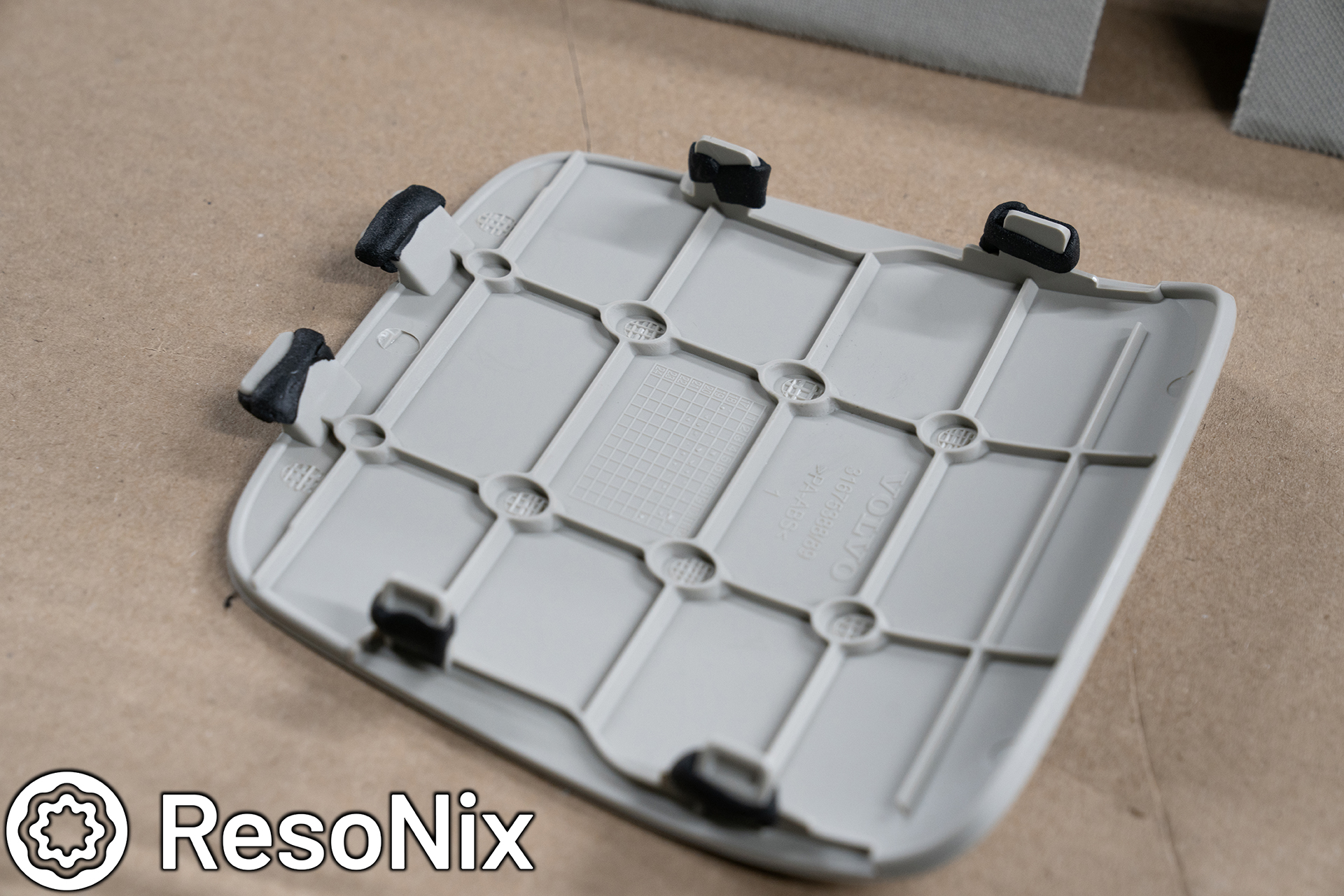
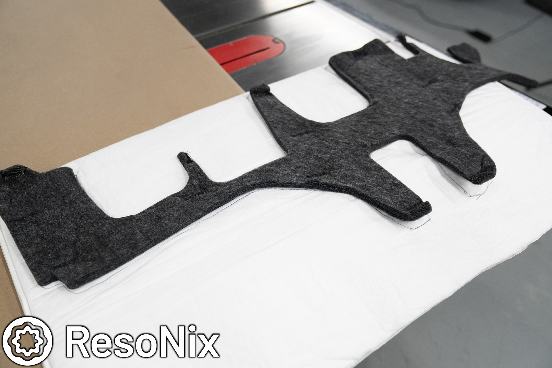
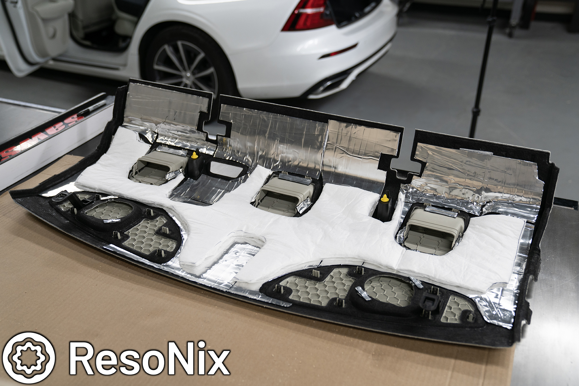
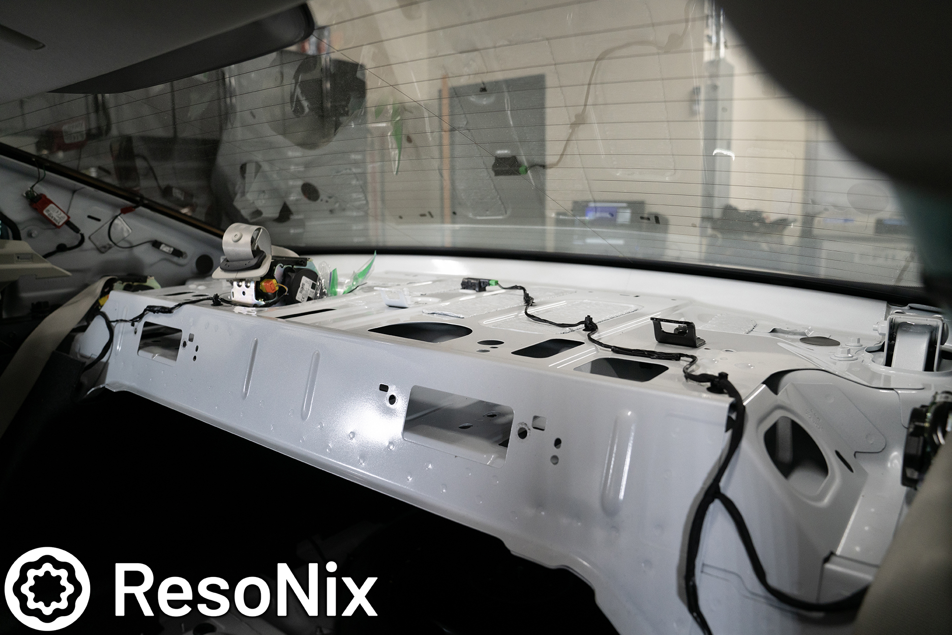
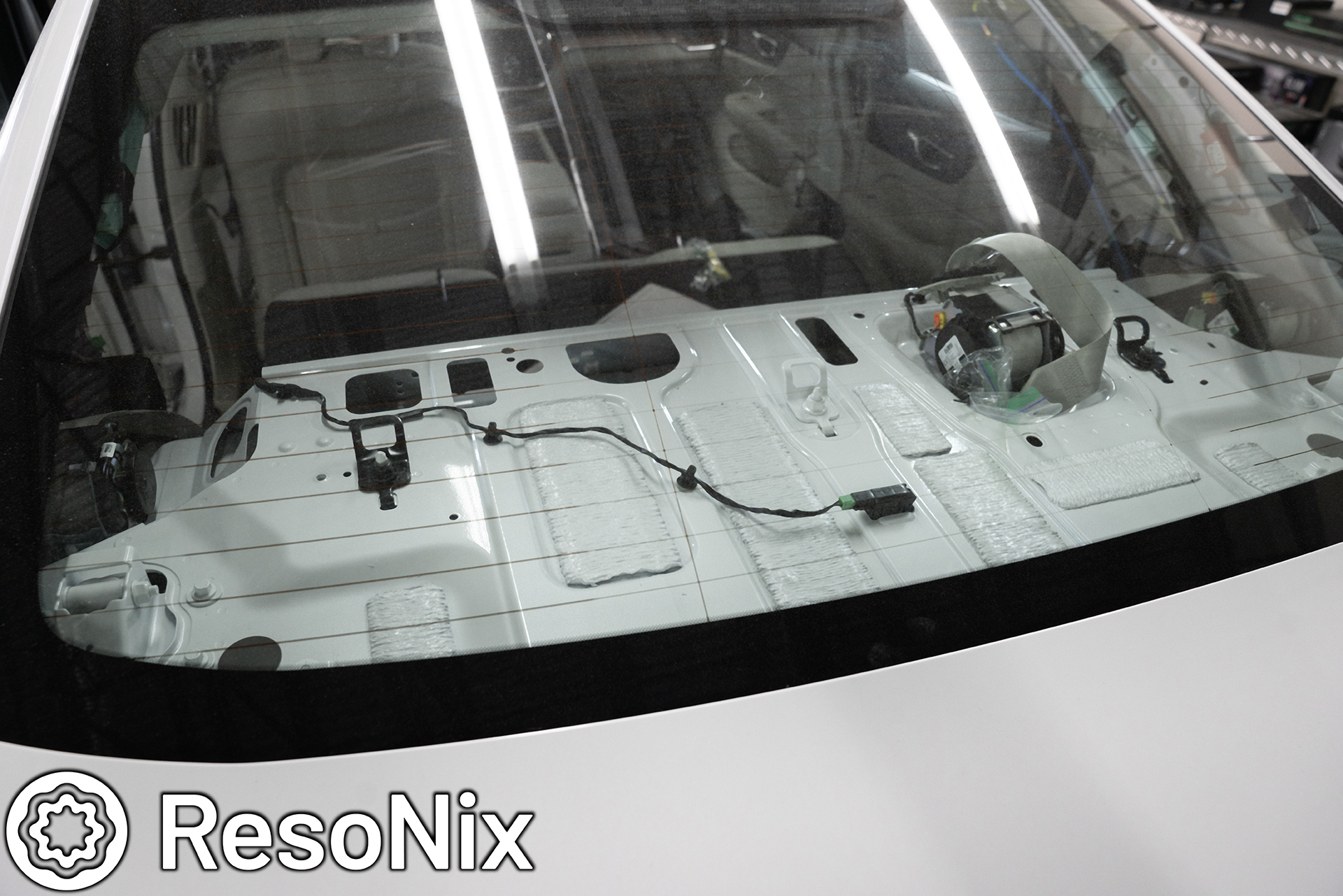
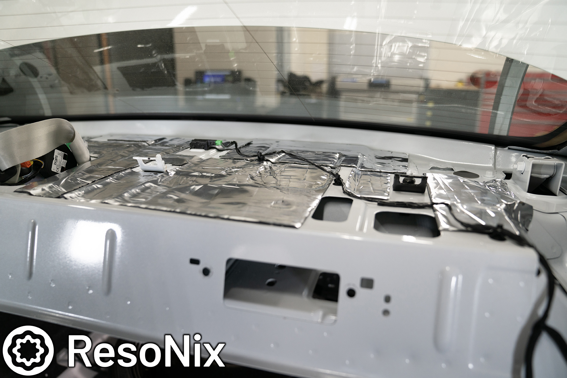
Next up was sound deadening the rear deck and rear deck trim panel. I started with the trim panel. Pictured here is the back side of it. You will see a thin OEM sound absorbing material. This fits into the memory foam piece that is molded between the rear deck and the back side of this rear deck trim, so this was a good guide for cutting out with our ResoNix Fiber Mat 25, which is a much better sound absorber than polyester based sound absorbers. The reason for this, the fibers for polyester sound absorbers are much larger in size than what we have with our ResoNix Fiber Mat. This means that sound energy is less likely to vibrate them as it passes through the material, which means it cannot convert as much sound energy into mechanical and thermal energy. This equates to a less effective sound absorber, and is why we opted to replace it with ResoNix Fiber Mat 25.
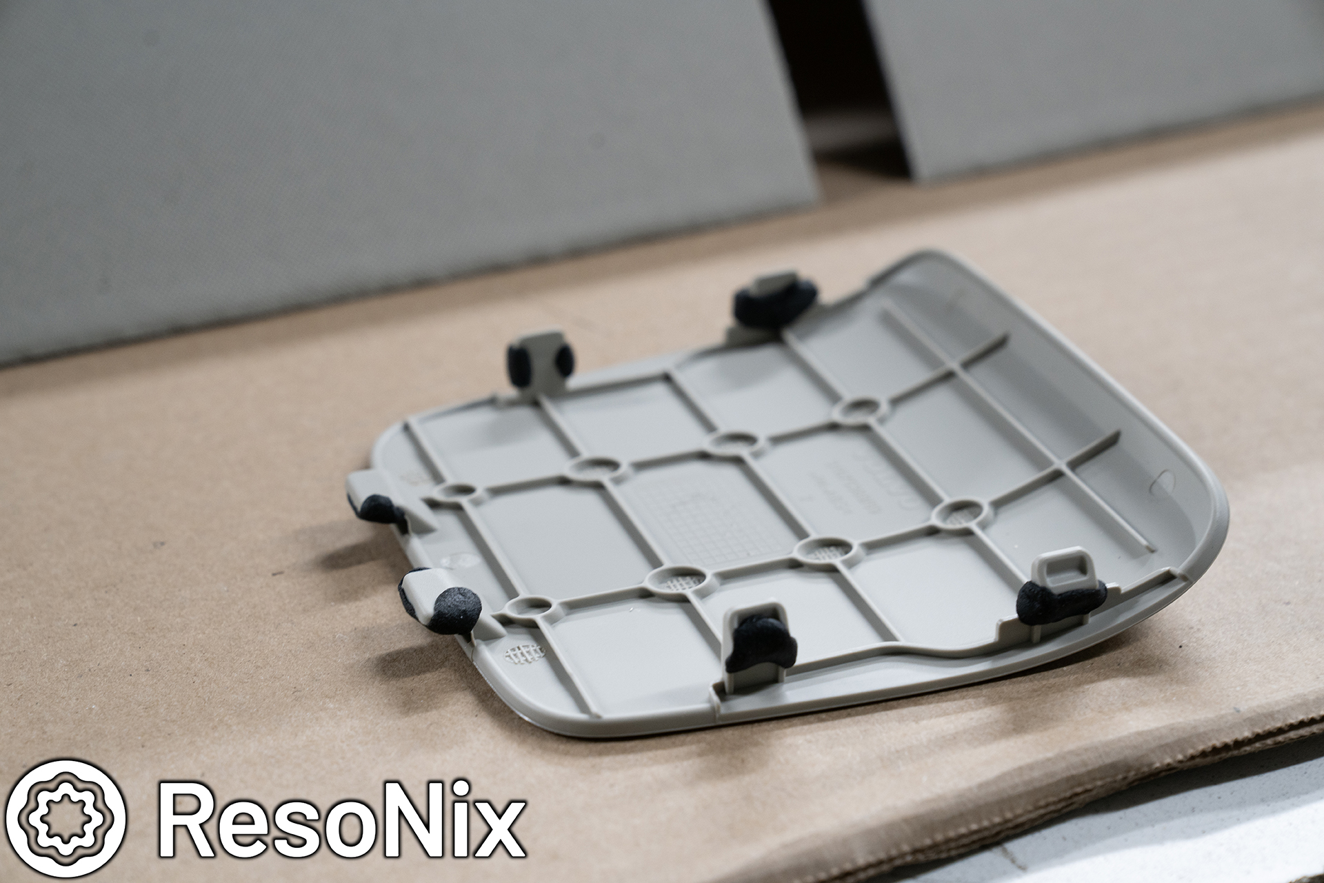
The child seat hook trim and their covers on the rear deck are also a problem. They are secured to the rear deck trim in a way that promotes rattles. Their covers also are prone to rattling against them. These will be dealt with accordingly.
First, the OEM sound absorber was removed, and ResoNix Mega CLD Squares were installed onto the back side of the rear deck trim. This reduces the amount that the panel can resonate, which will reduce rattles, as well as make the subwoofers more accurate as their resonance will no longer be able to color their output.
Next up, dealing with the child seat hook trims and their covers. You can see how loosely this and the cover are secured together, and being so light and flimsy, will be a problem. I know they were in my car before I treated them, so I took care of these before they were a problem here.
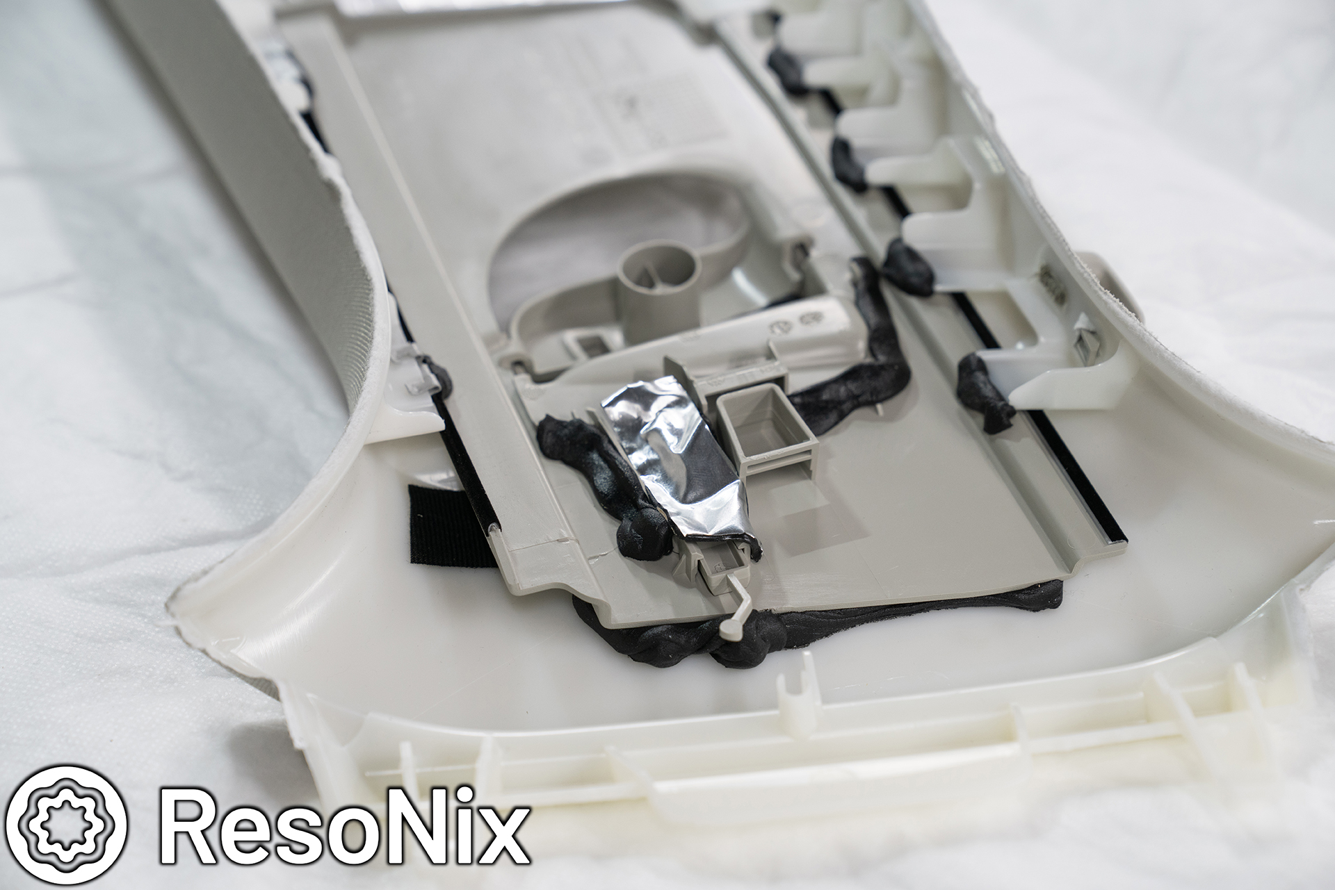
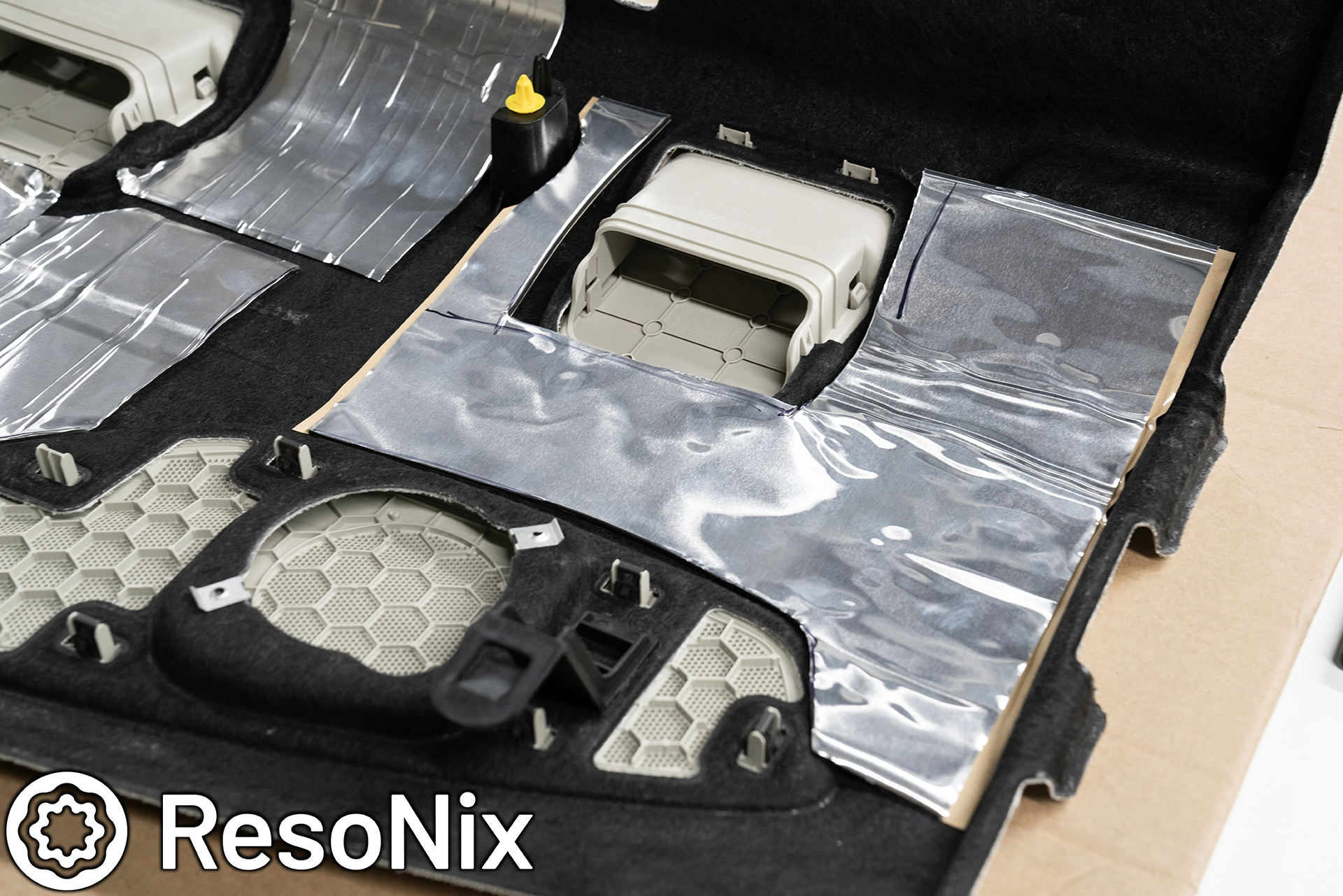
First things first, small pieces of ResoNix CCF Decoupler 3S to decouple the cover from the trim in the areas it could vibrate against. The CCF3S is thin and soft enough to work with these super tight tolerance areas that cannot handle extra material and extra pressure.
Then, I used ResoNix Butyl Rope around its contact points. This helps secure it in place, as well as decouple it from any surfaces it may rattle against.
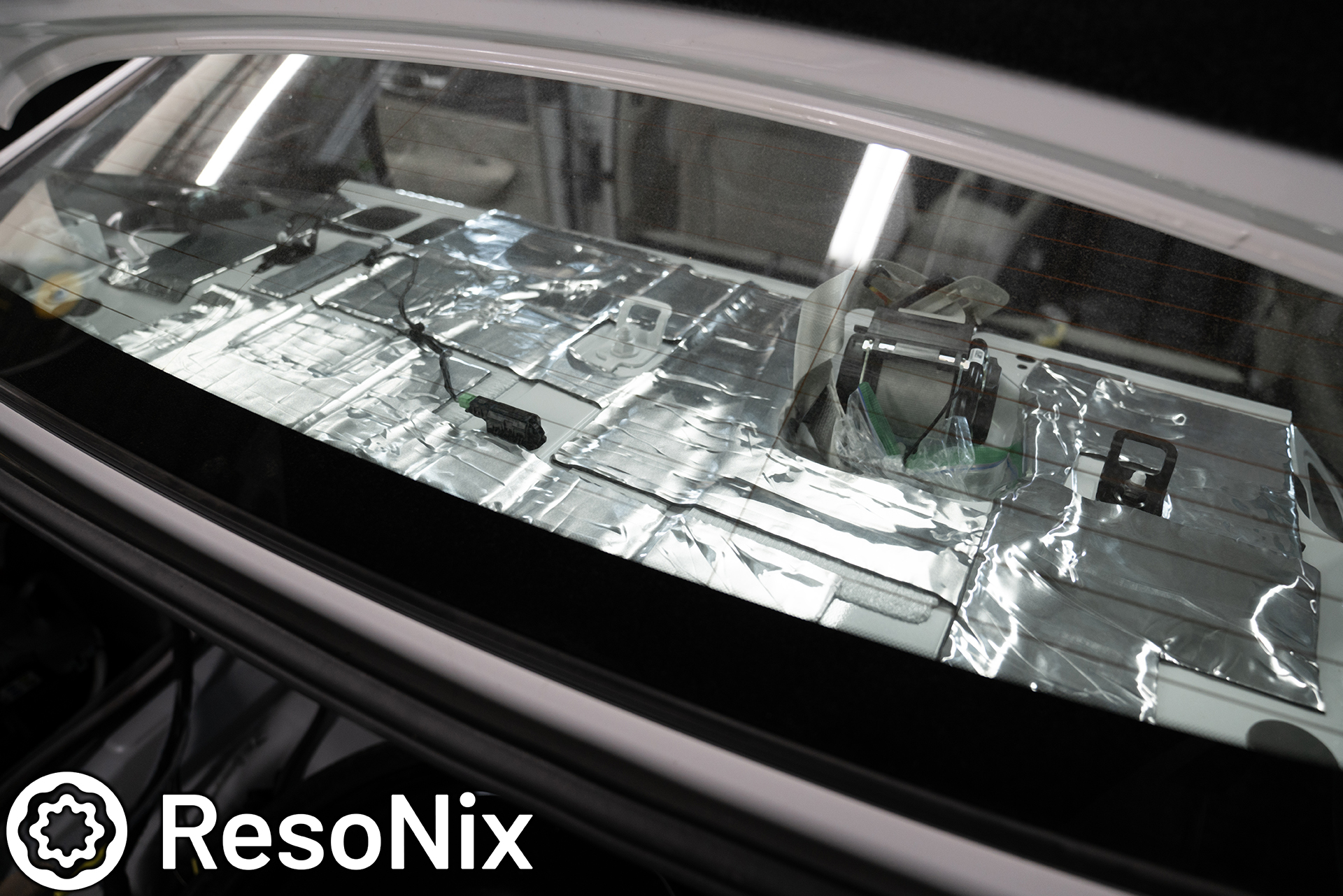
Next up, tracing the OEM sound absorber onto ResoNix Fiber Mat.
ResoNix Fiber Mat installed. It is now ready for installation. But not before we treat the rear deck structure.
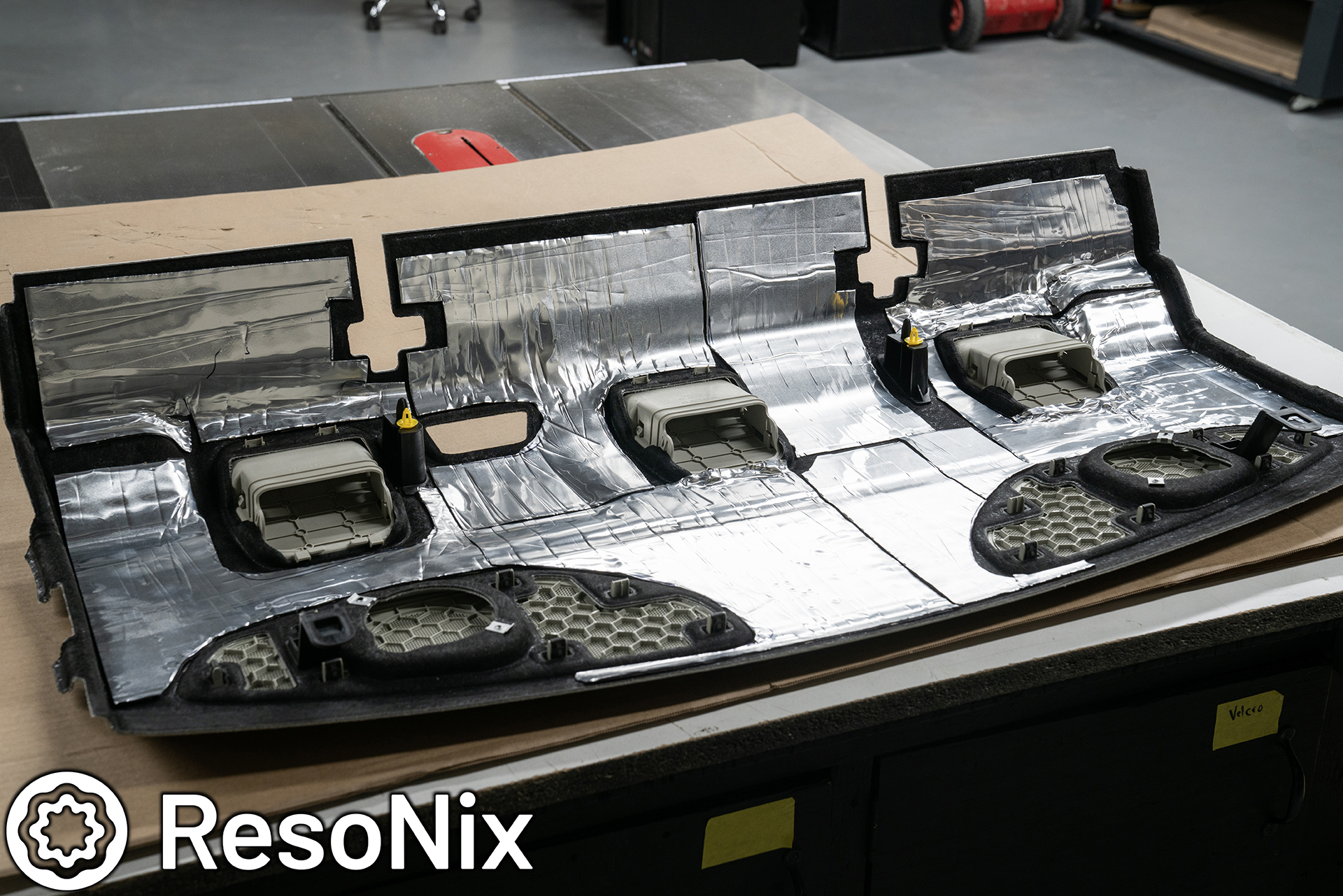
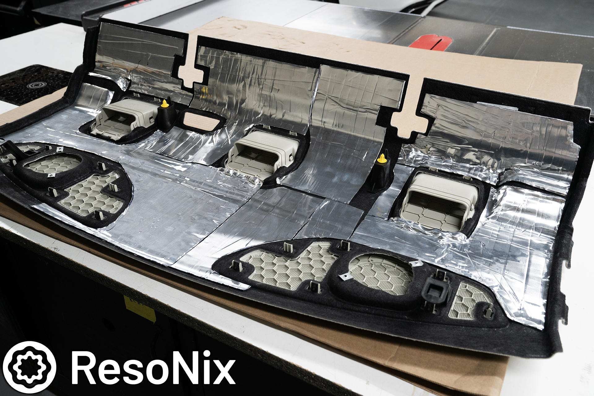
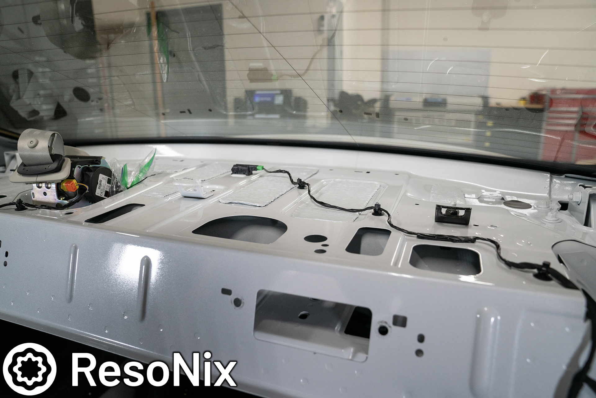
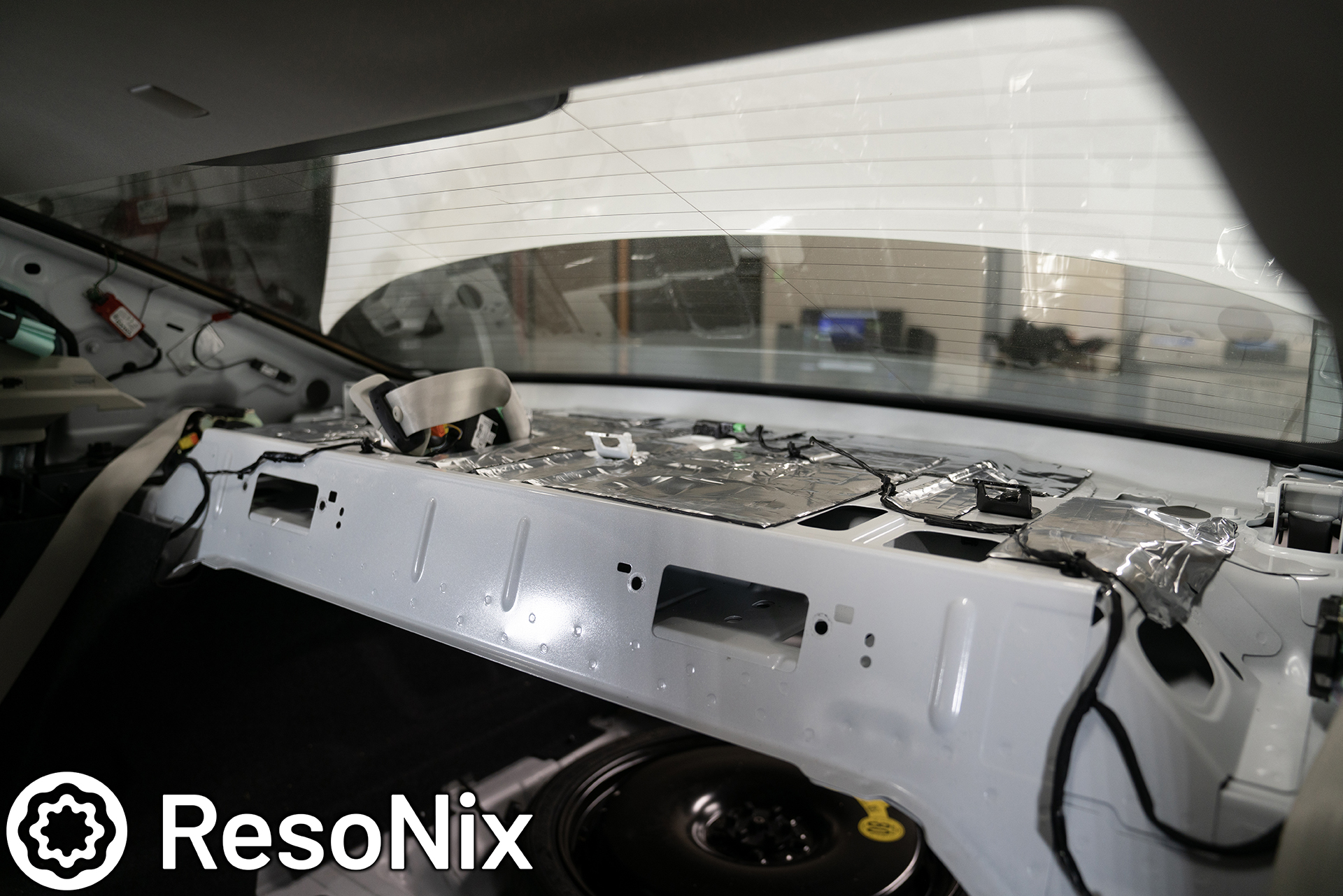
Here we can see the bare rear deck. It is mostly a thin piece of steel, and with the amount of bass we will have in this car, it will definitely resonate. I opted to use ResoNix Mega CLD Squares here to get the best performance for resonance reduction possible. I did as much coverage as I possibly could using as large of pieces as I reasonably could. Remember, a bunch of small pieces is not nearly as effective as one larger piece.
ResoNix Mega CLD Squares installed. I made sure to take note of and steer clear of any holes that the rear deck trim clips into, and any wiring and sensors that may be here. I also clearly stayed away from the seat belts as we do not want to hinder their function.
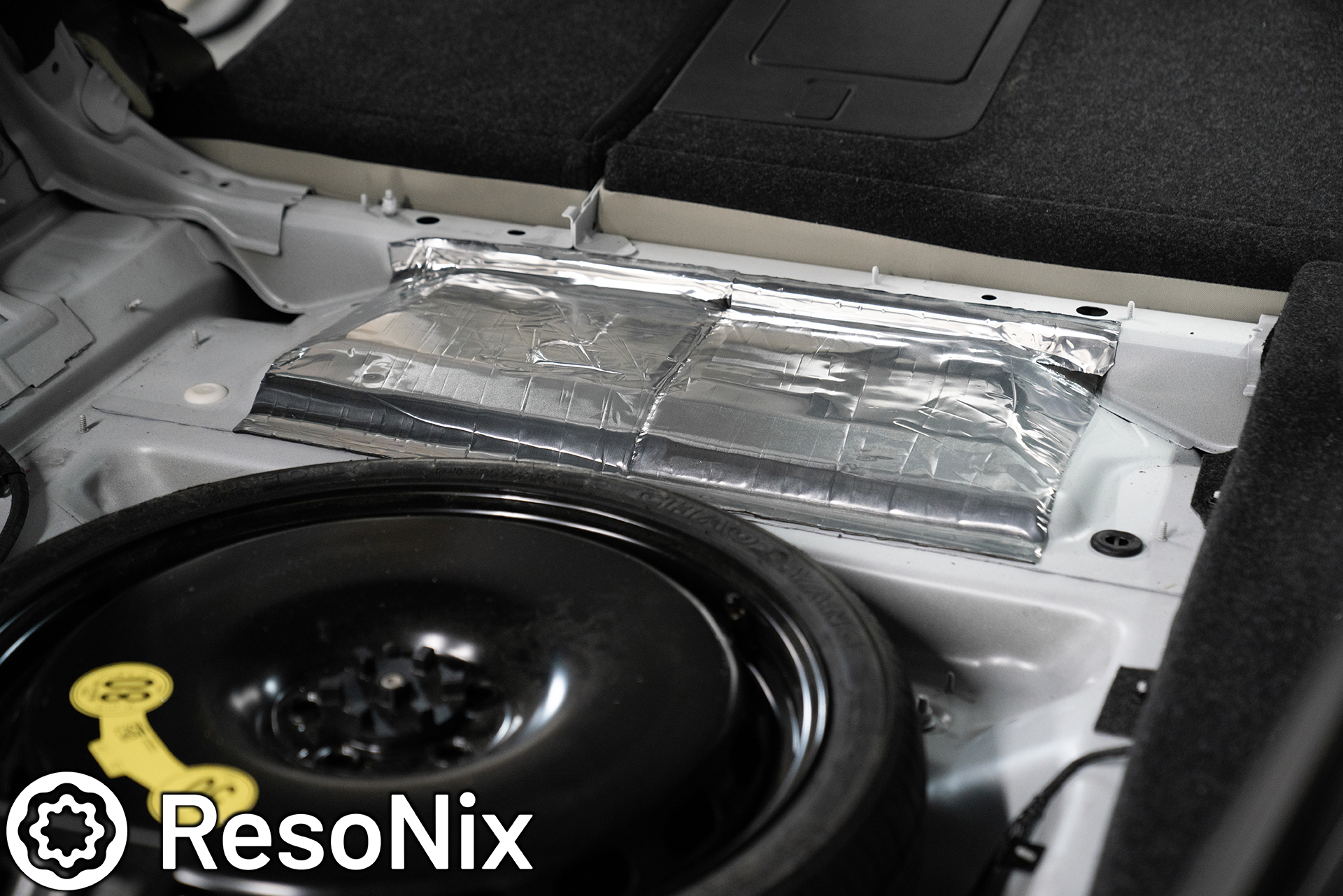
I also installed some ResoNix Mega CLD Squares on the floor right where the subwoofer enclosure will reside.
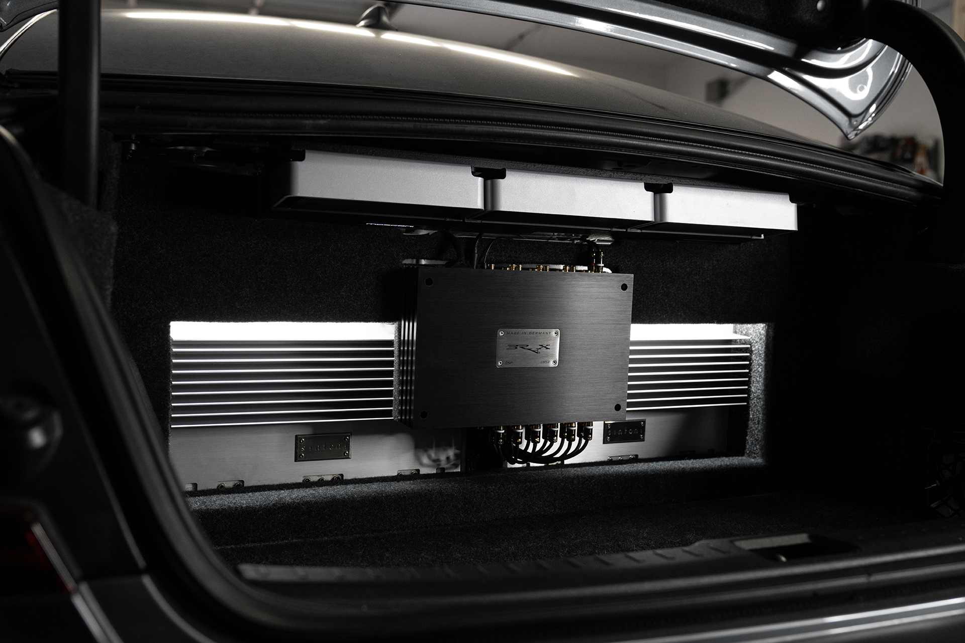
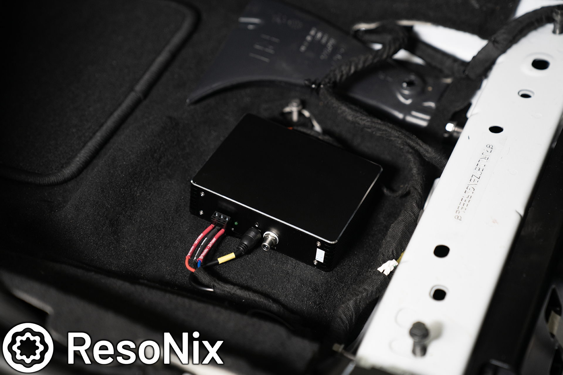
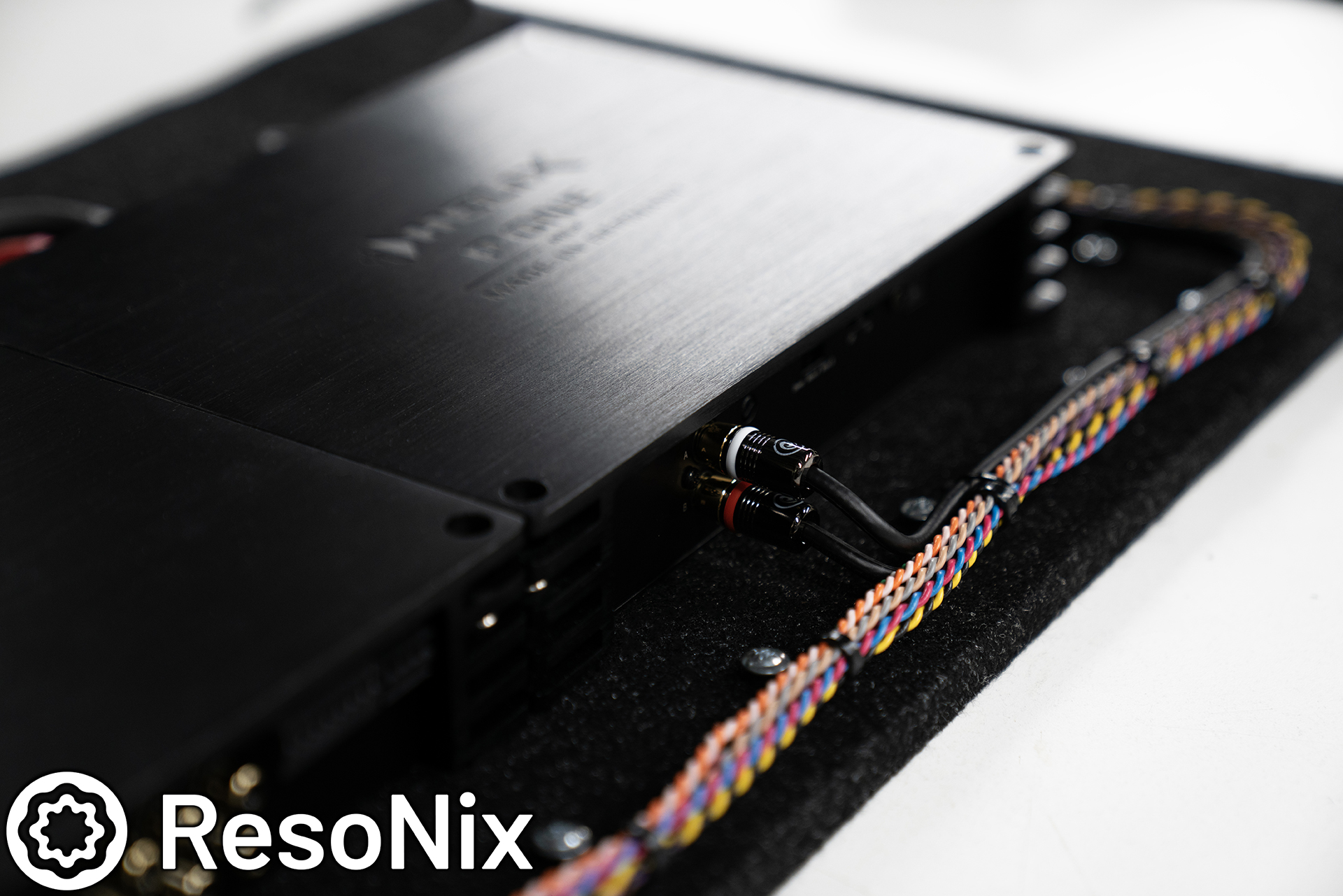
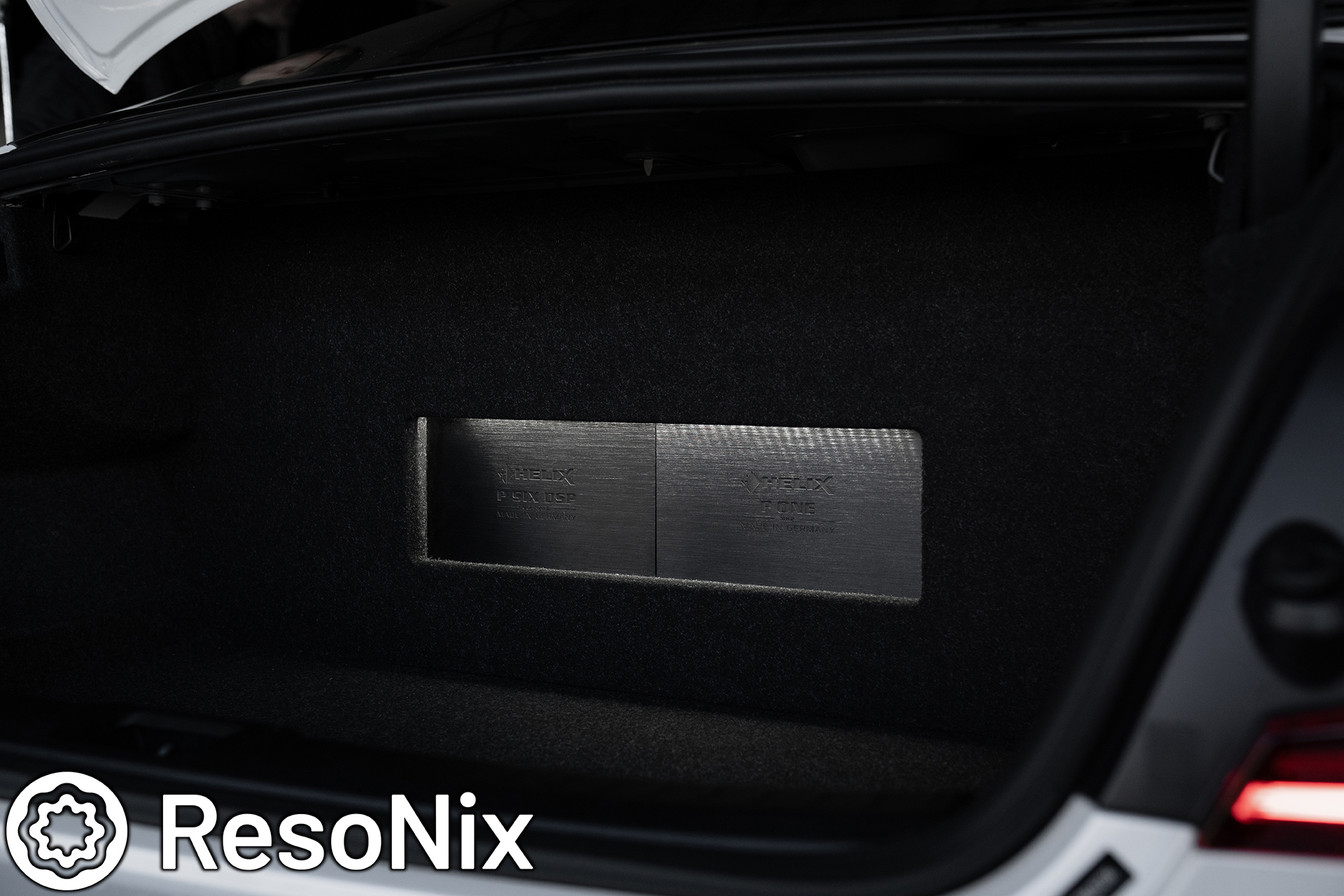
Next up, the amplifier rack and its wiring. I did my absolute best to keep this as clean and serviceable as possible. As you can see, we used the Deutsch Connector for all of the speaker wires, conductor wires, and wires for the MOST150 interface. The RCA’s from the P Six Ultimate from the P One Mk2 are of course the ResoNix Solderless Custom RCA System. We opted for RCA instead of optical for two reasons. First, easier to set up for headroom and overlap in the gain structure to get the output we want. Second, perfect length. We do not have custom length custom optical cables…. yet.
As mentioned earlier, we used an Anderson connector on the main power and ground leads as well for easy disconnect there, and also used an optical connector for easy disconnect of the optical input signal.
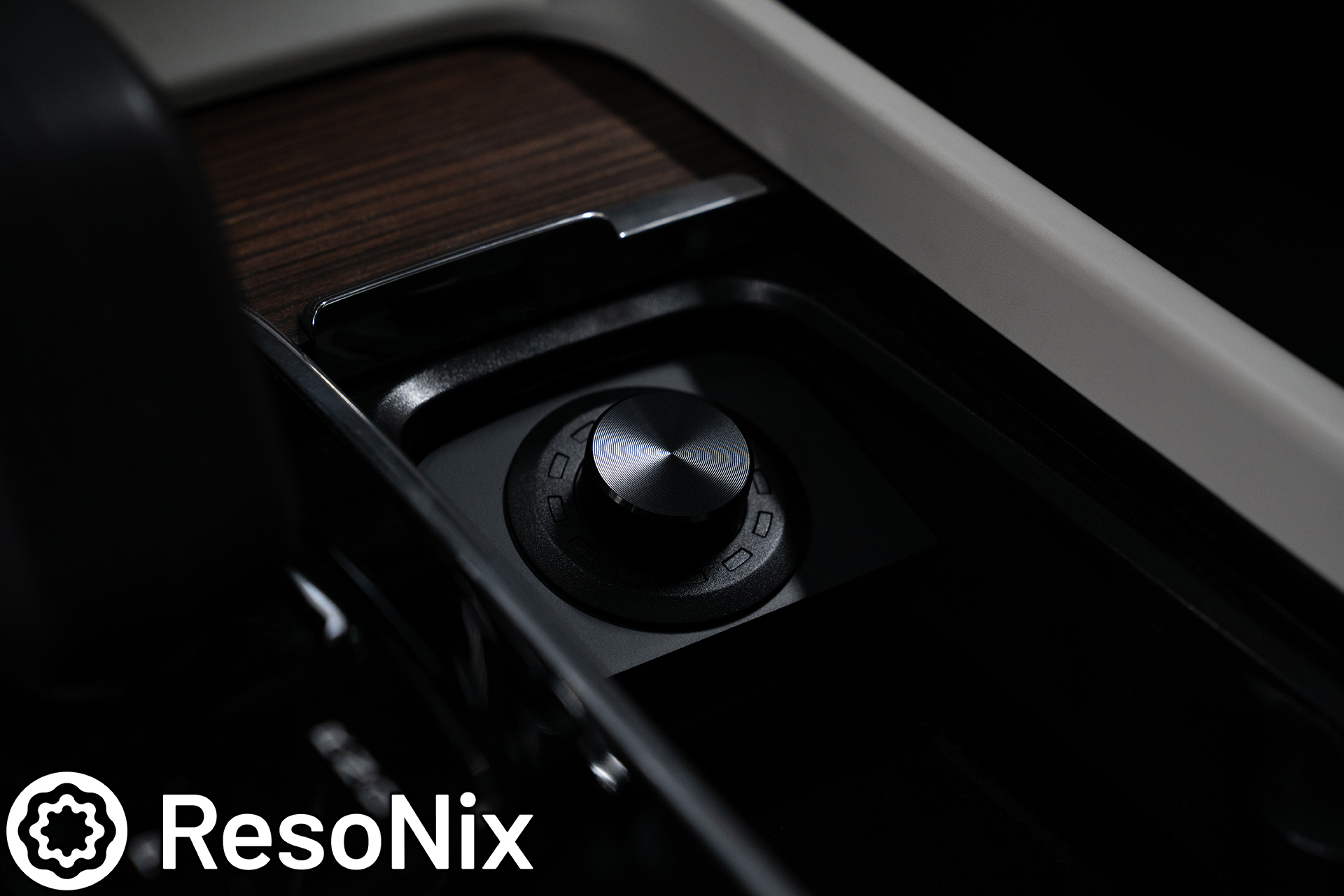
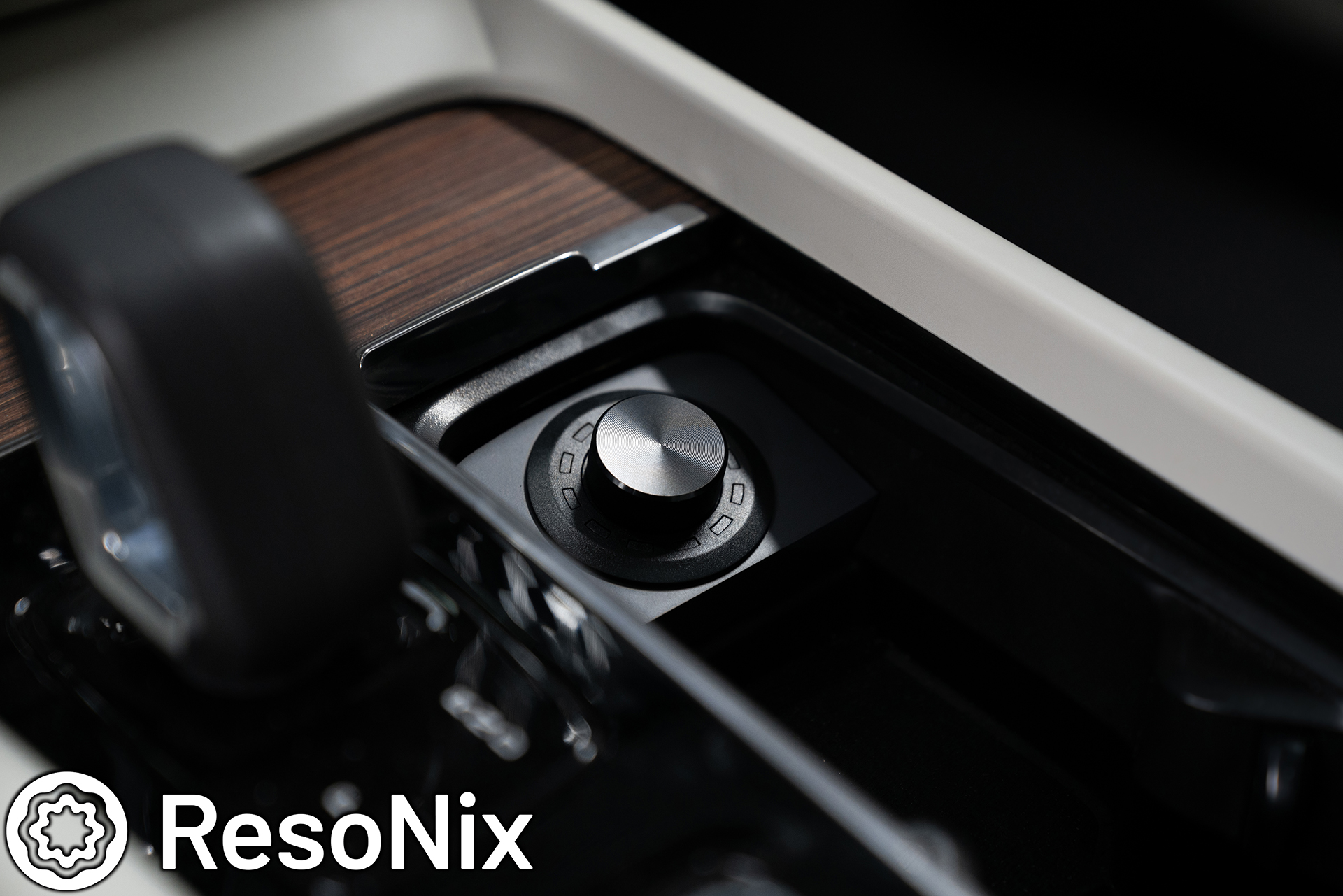
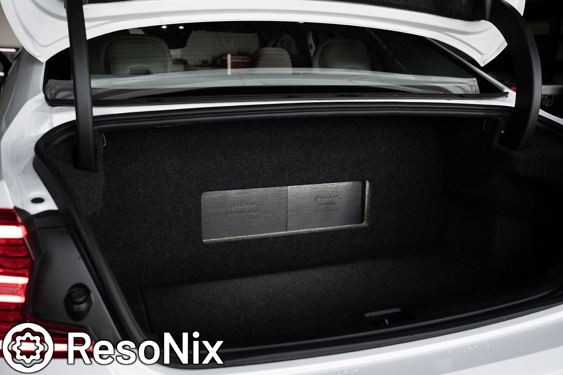
The Helix Conductor was added to where the OEM cigarette lighter socket originally resided. I made a custom housing for it that fit right into the location, painted it a matching satin black, and was able to fit it in a way that looks factory, allows the OEM cover to hide it when needed, and most importantly, is easy to reach and operate.
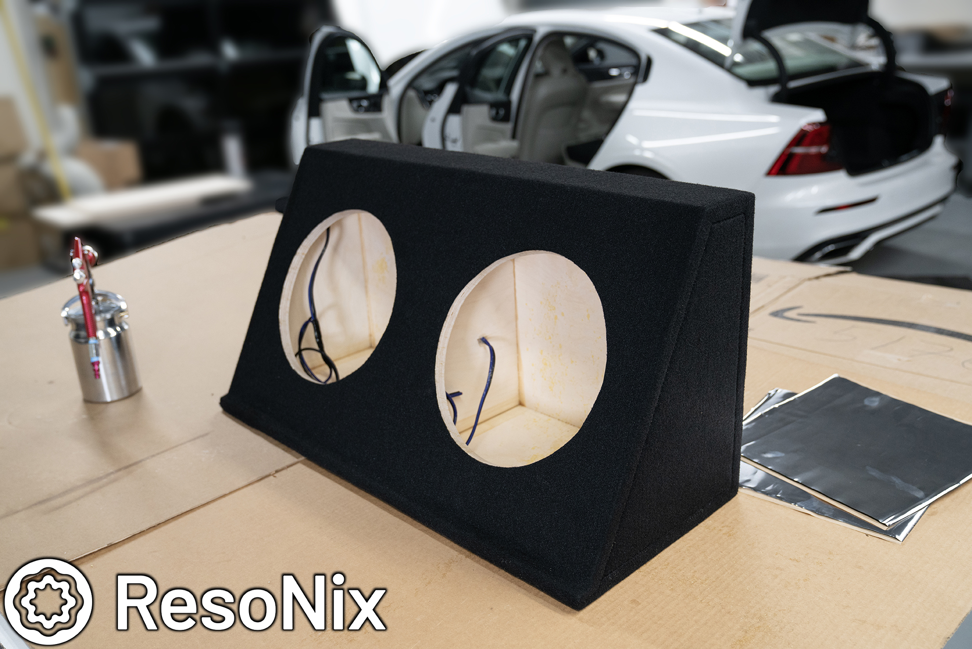
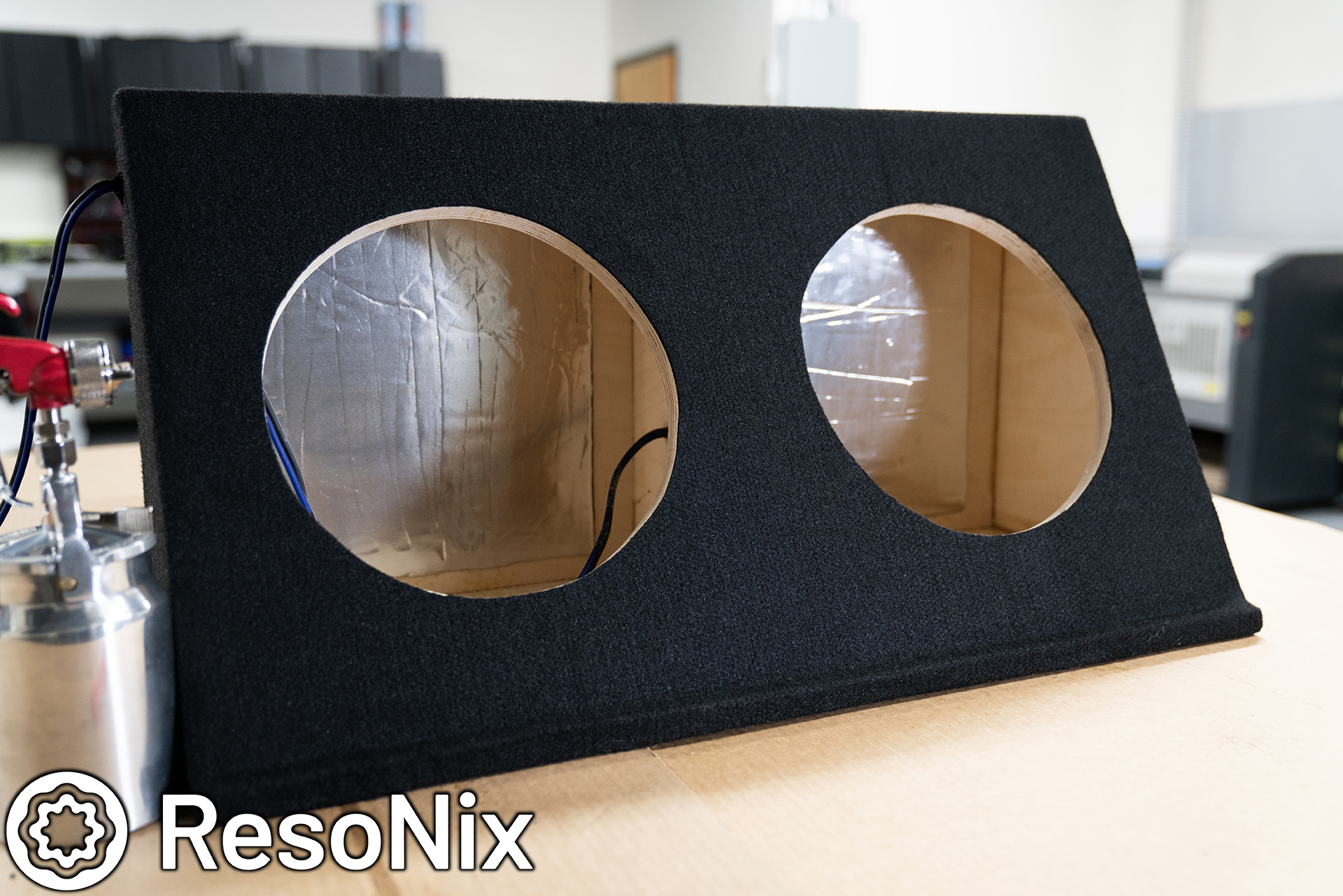
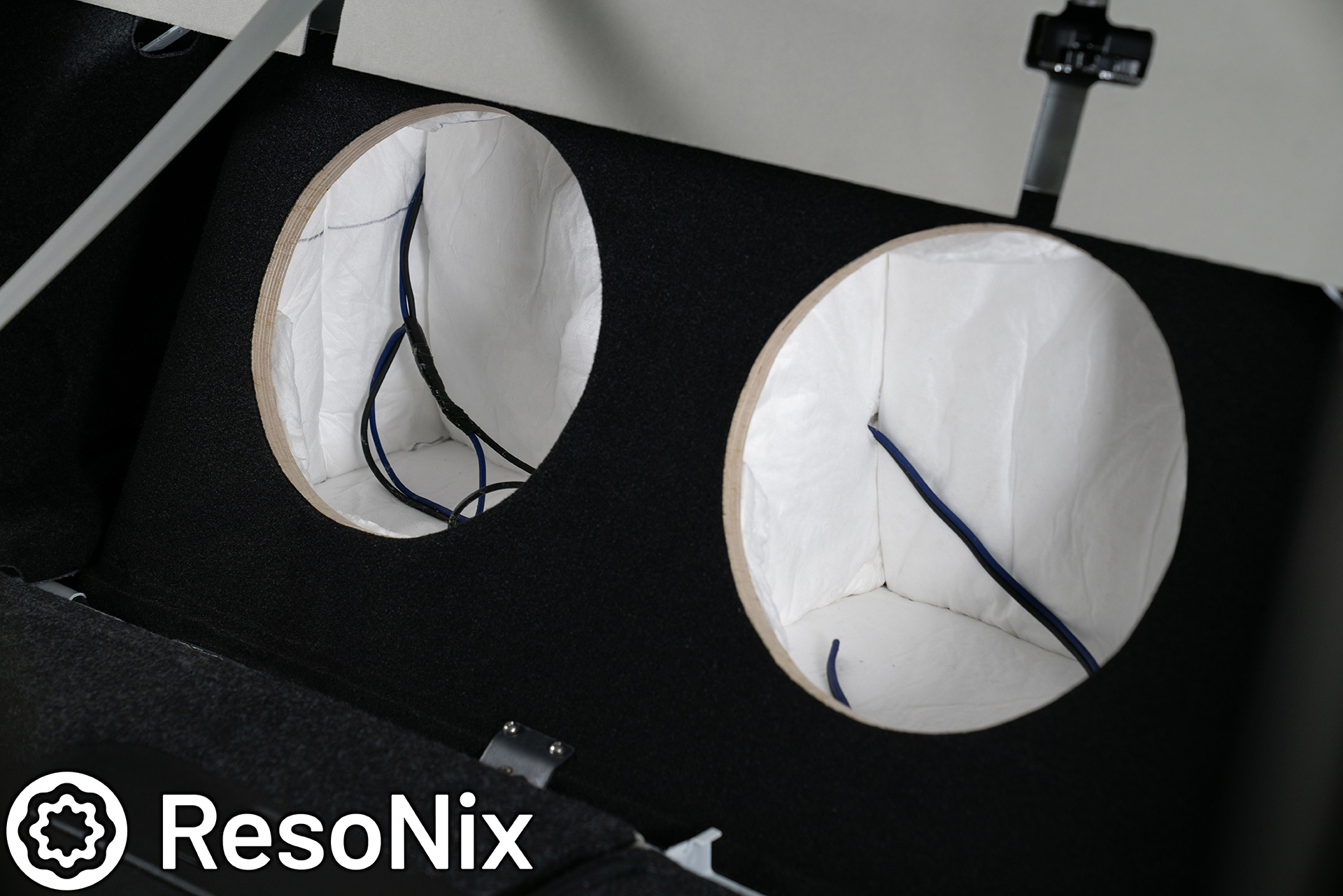
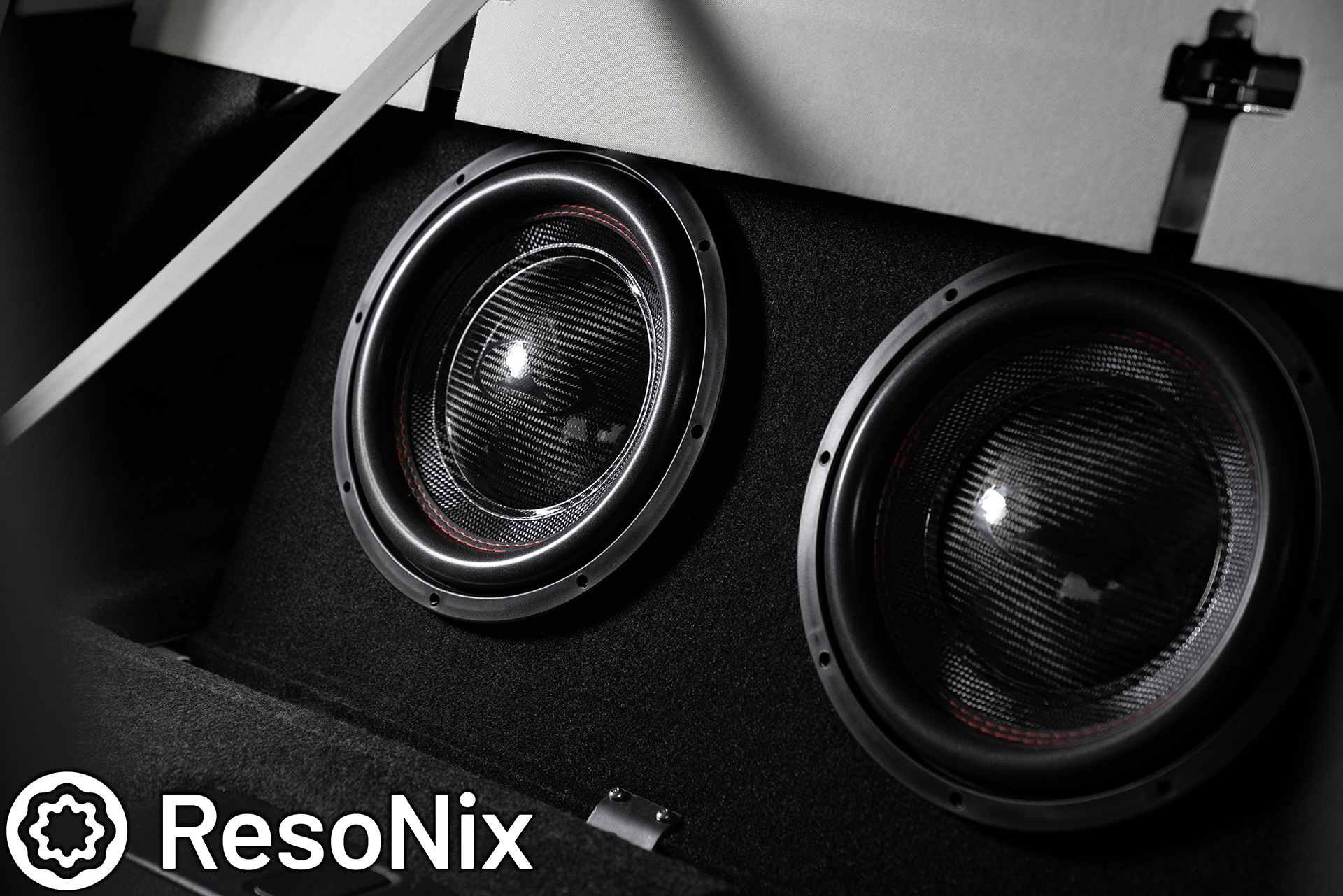
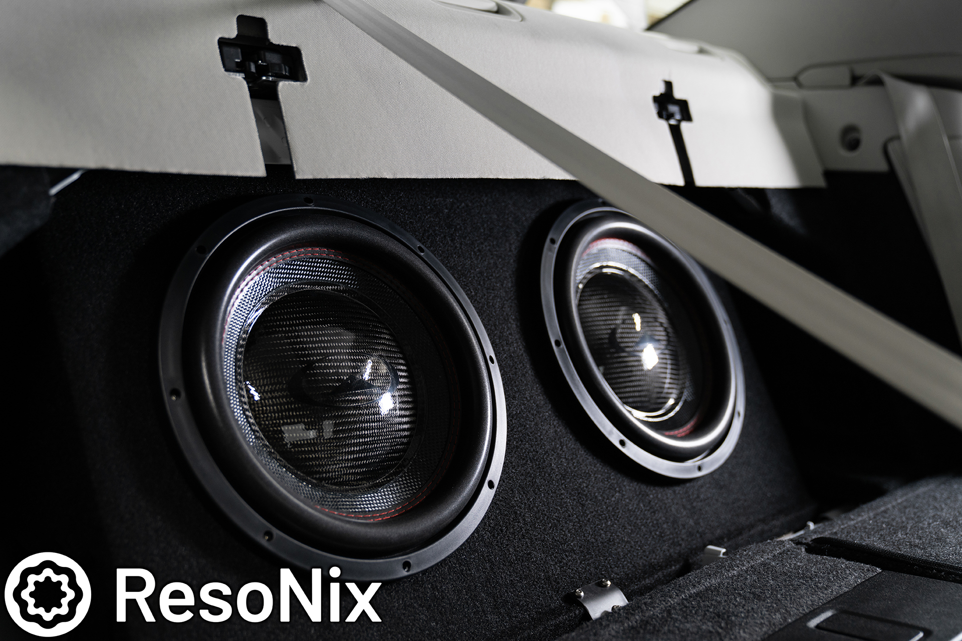
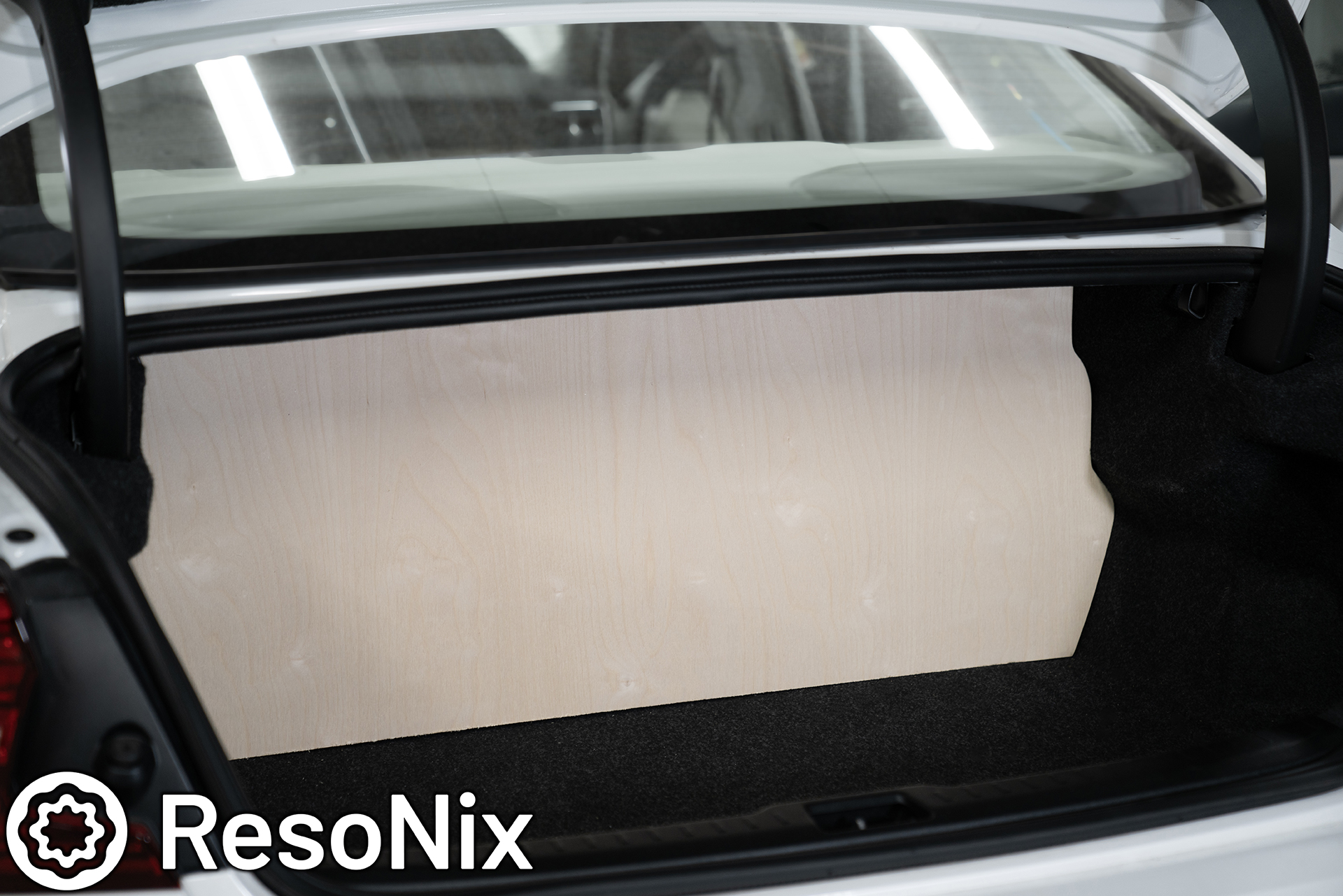
Up next was the subwoofer enclosure. Since we needed the spare tire to still be accessible and the customer wanted a good amount of output from the subs, this was a big ask considering the trunk size in this vehicle is very small. Its quite possibly my only gripe with owning this car. That leaves us with having to build a pretty dang small sealed enclosure. It ended up being 2 separate chambers at 0.9 cubic feet per side. Not much, but the Audiomobile Encoure 12’s handled it VERY well. As a matter of fact, they played flat down to 10hz in this car with this enclosure. Incredible.
The enclosure was constructed out of 18mm void free baltic birch, and was finished in black carpet.
I also treated the inside with ResoNix CLD Squares, and ResoNix Fiber Mat 45. Some will say this is unnecessary. I say car audio as a whole is unnecessary. So if its all unnecessary, might as well do everything you can to make the time, money, and effort worth it. All of the small things add up, and the sum is a better sounding car than it would have been otherwise.
Yes, the enclosure shouldn’t resonate, and it “didn’t” without it. But the truth is, EVERYTHING resonates. And enclosure like this just has a very high resonant frequency. Constrained Layer Dampers don’t change the resonant frequency like some think. Instead, they use sheer resistance to actually reduce resonance as a whole. So yeah, knocking on it, there is a very audible difference. Weather it makes the subwoofers perform and integrate into the system as a whole better or not, who knows. It only took an extra few minutes and a few extra pieces to do the larger panels on the inside.
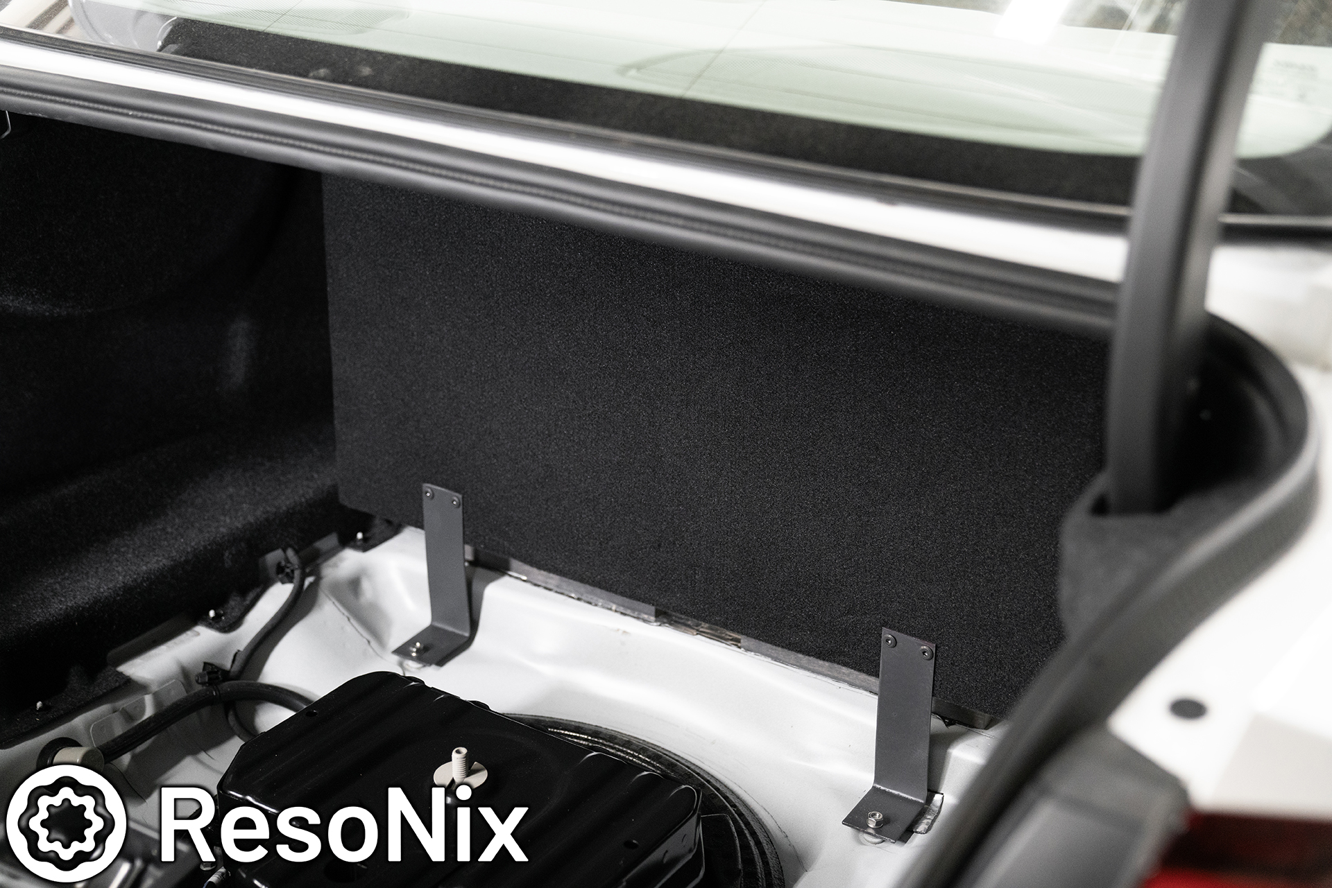
The enclosure was secured in 3 locations. Two in the rear and one in the front. The locations in the rear actually use OEM bolts that reside right outside of the spare tire. The one in the front, I used an M8 Riv-Nut and Bolt to hold it in place.
Fiber Mat 45 was installed over the entire interior of the box in 1 layer. Fiber Mat 45 has proven to be MUCH more effective than standard polyfill, again, due to its extremely small fibers that it consists of. These smaller fibers, being much easier for passing sound energy to vibrate, allow it to absorb sound more efficiently.
The Audiomobile Encores… very impressed with these. The build quality, the output, the sound quality, the low frequency extension, even in a ridiculously small enclosure, etc… I will definitely be using these again.
The subwoofers were also installed with Stainless tamper-resistant screws.
Update! Uploaded 2 days after this build was initially posted.
I am glad to see that so many are excited to see us back at it. I’m also glad to see people interested and curious in what we are doing to the point where I have received countless questions and comments on the Volvo S60 install that I recently posted. The most common question is, “How are the Audiomobile Encore subs?”… To summarize it, this is my first time using them, and I will be using them again. Even though we had to place them in an extremely small enclosure, they played flat down to 10hz, with an F3 of just below 8hz, which I assume is only due to the natural roll off of the DSP/amplifier. I cant wait to do more installs with these.
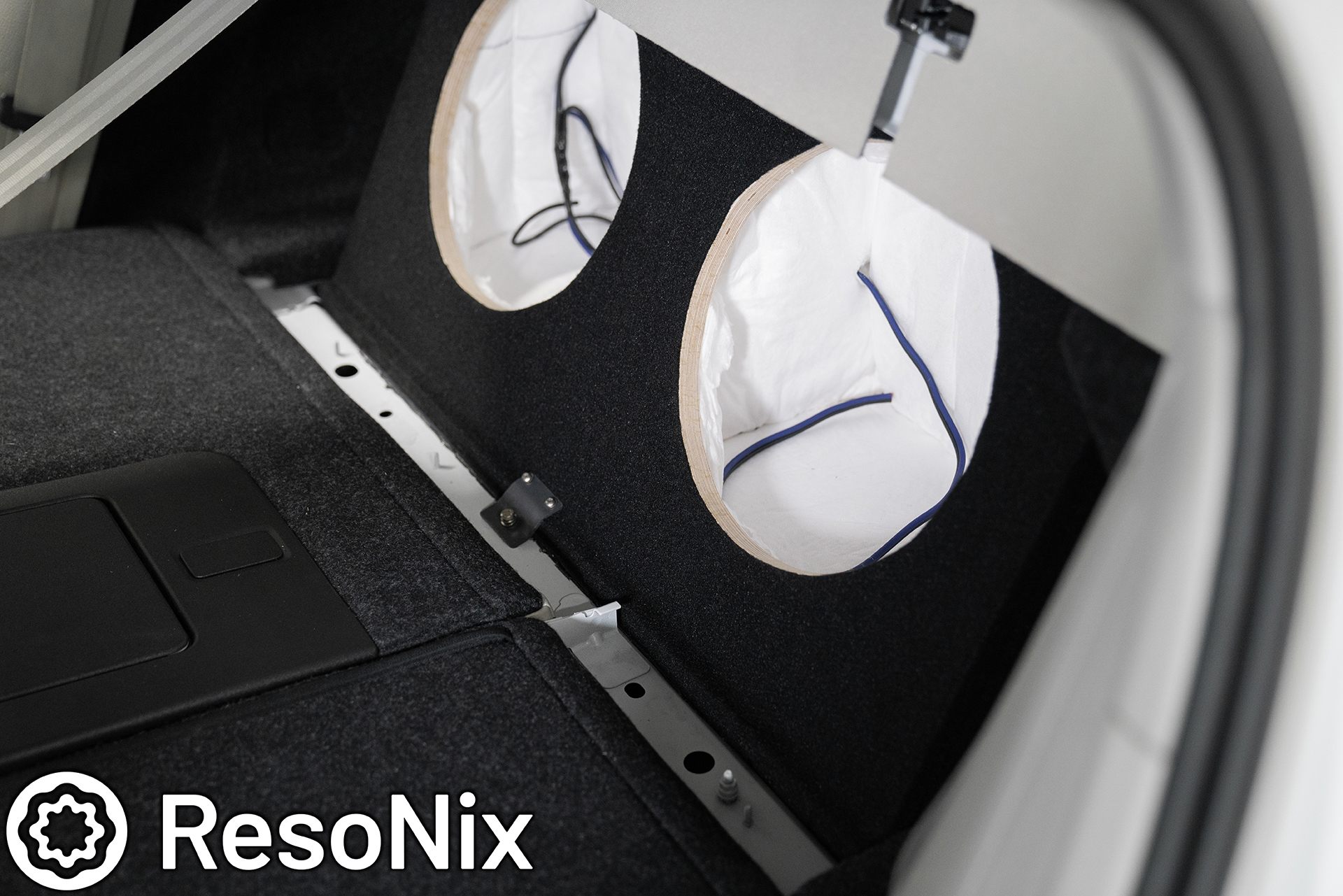

The amplifier rack secures to the back of the enclosure, and all of the wiring clips right in within seconds.
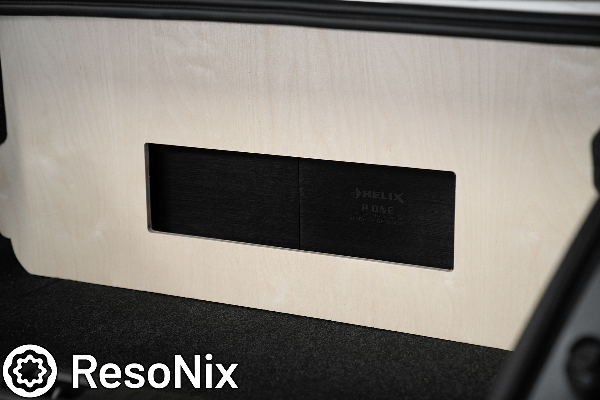
A beauty panel was constructed for the amplifier rack. At first, we were going to hide everything. That was, until the client saw my trunk and wanted something similar that showed off the amps in a very simple yet clean fashion. This panel (and the amplifier rack) were also constructed out of baltic birch.
Once the beauty panel was complete, it was upholstered with matching charcoal carpet, and was fitted with a subtle white LED strip above the amplifiers. The panel secures via pressure on the sides of the amplifiers, as well as on the sides of the trunk panels. It fits seamlessly and is secure, yet removes in seconds to access the amplifier rack.
That wraps it up for our first car audio install at our new location! If you have any questions, feel free to ask. If you are interested in having a high-performing sound system installed or an already existing one improved upon in your vehicle, feel free to reach out! Again, I am very excited to be back doing this, and am especially grateful that I am able to make this a fun side-gig as opposed to my full time career.
2019 Volvo S60 R-Design – ResoNix Sound Solutions Demo Sound System Elevating Sound and Functionality: The Ultimate 2019 Volvo S60
How to Sound Deaden a Car: A Comprehensive Guide to Quieter Rides Are you tired of road noise disrupting your
ResoNix Sound Solutions is a company with a specialty in high-end car audio and automotive sound treatment that offers top quality products and services that provide superior performance in their respective categories. No gimmicks, no baseless claims, no nonsense. Constrained layer dampers, sound absorbers, decouplers, noise barriers, and car audio DSP tuning and consultation services are part of our line-up with a focus on data-backed, solutions-based products developed by professional enthusiasts, for enthusiasts.
